 |
am3zzw00004300
ENGINE REMOVAL/INSTALLATION [MZR-CD (RF Turbo)]
id0110f1800400
1. Remove the engine cover. (See TIMING BELT REMOVAL/INSTALLATION [MZR-CD (RF Turbo)].)
2. Disconnect the negative battery cable.
3. Drain the engine coolant and transaxle oil.
4. Remove the both front tires.
5. Remove the under cover and both splash shield.
6. Remove the air cleaner and air hose. (See INTAKE-AIR SYSTEM REMOVAL/INSTALLATION [MZR-CD (RF Turbo)].)
7. Disconnect the fuel hose. (See BEFORE SERVICE PRECAUTION [MZR-CD (RF Turbo)].)
8. Remove the front pipe. (See EXHAUST SYSTEM REMOVAL/INSTALLATION [MZR-CD (RF Turbo)].)
9. Remove the battery and tray. (See BATTERY REMOVAL/INSTALLATION [MZR-CD (RF Turbo)].)
10. Set the shift cable, select cable and clutch release cylinder parts related to the transaxle out of the way. (See MANUAL TRANSAXLE REMOVAL/INSTALLATION [A26M-R].)
11. Remove the front crossmember. (See FRONT CROSSMEMBER REMOVAL/INSTALLATION.)
12. Remove the vacuum hose and the heater hose.
13. Disconnect the P/S oil pump pressure pipe and P/S oil pump relief hose from the P/S oil pump side. (See POWER STEERING OIL PUMP REMOVAL/INSTALLATION [MZR-CD (RF Turbo)].)
14. Remove the drive belt. (See DRIVE BELT REMOVAL/INSTALLATION [MZR-CD (RF Turbo)].)
15. Remove the A/C compressor with the pipe still connected. Position the A/C compressor so that it is out of the way. Use wire or rope to secure it. (See A/C COMPRESSOR REMOVAL/INSTALLATION [MZR-CD (RF-Turbo)].)
16. Remove the generator. (See GENERATOR REMOVAL/INSTALLATION [MZR-CD (RF Turbo)].)
17. Remove the front drive shaft from the transaxle.
18. Remove the cooling fan component. (See RADIATOR REMOVAL/INSTALLATION [MZR-CD (RF Turbo)].)
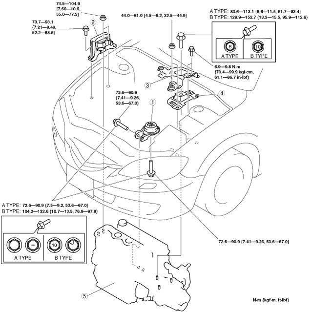
19. Remove in the order indicated in the table.
20. Install in the reverse order of removal.
21. Fill the engine coolant and transaxle oil.
22. Bleed the air from the fuel line. (See AFTER SERVICE PRECAUTION [MZR-CD (RF Turbo)].)
23. Start the engine and:
24. Perform a road test.
25. Reinspect the engine oil, engine coolant, transaxle oil, and P/S fluid levels.
am3zzw00004300
|
|
1
|
No.1 engine mount rubber
|
|
2
|
No.3 Engine mount
|
|
3
|
Battery bracket
|
|
4
|
No.4 Engine mount rubber
|
|
5
|
Engine, transaxle
|
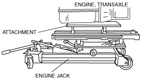
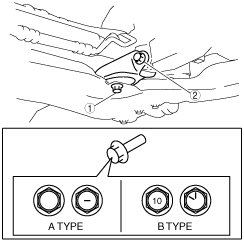
No.3 Engine Mount and No.4 Engine Mount Rubber Removal Note
1. Secure the engine and the transaxle using an engine jack and attachment as shown in the figure.
am3zzw00004014
|
No.3 Engine Mount and No.4 Engine Mount Rubber Installation Note
1. Secure the engine and the transaxle using an engine jack and attachment as shown in the figure.
am3zzw00004014
|
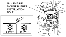
2. Install the No.1 engine mount rubber and No.4 engine mount rubber.
3. Tighten the No.4 engine mount rubber installation bolt as shown in the figure.
am3zzw00004603
|
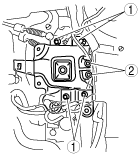
4. Tighten the No.4 engine mount rubber and battery bracket bolts and nuts in the order as shown in the figure.
am3zzw00004016
|
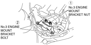
5. Tighten the No.3 engine joint bracket bolts and nuts in the order as shown in the figure.
am3zzw00004017
|
No.1 Engine Mount Rubber Installation Note
1. Remove the engine jack and attachment.
2. Tighten the No.1 engine mount rubber installation bolts in the order as shown in the figure.
am3zzw00009595
|