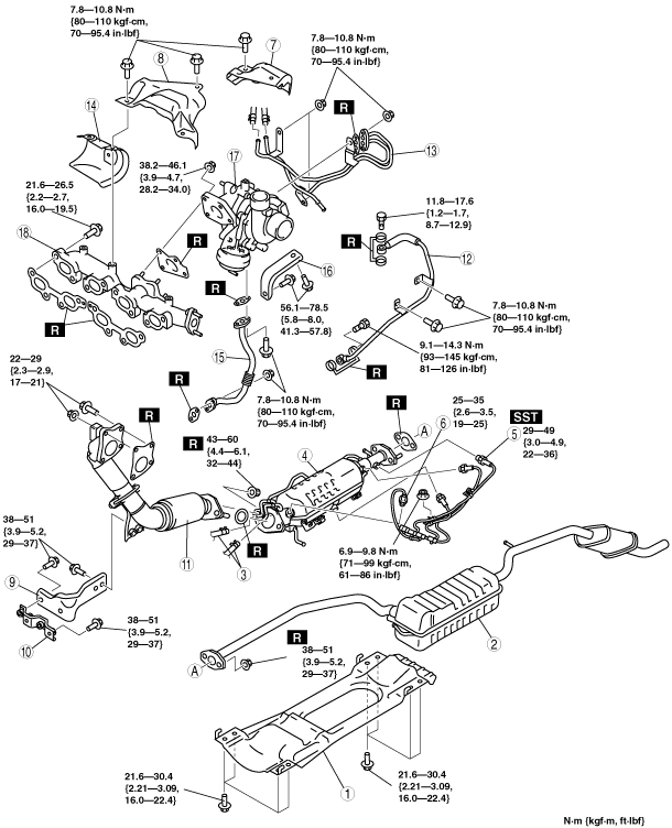
EXHAUST SYSTEM REMOVAL/INSTALLATION [MZR-CD (RF Turbo)]
id0115f1800200
-
Warning
-
• When the engine and exhaust system are hot, they can cause severe burns or injury. Turn off the engine and wait until they are cool before removing the exhaust system.
-
Caution
-
• Perform exhaust gas temperature sensor removal/installation only when inspection or replacement is required, such as when DTCs for the sensor are displayed, because it may cause exhaust gas leaks. If removal or installation/removal is performed, always verify that there is no exhaust gas leak after reinstallation.
-
Note
-
• If the diesel particulate filter indicator light is flashing and/or the MIL is illuminated, perform the symptom troubleshooting and verify the DTC of the diesel particulate filter system by using the M-MDS before removing parts. If any DTCs are displayed, perform troubleshooting according to the corresponding DTC inspection.(See
DTC TABLE [MZR-CD (RF Turbo)].)(See
SYMPTOM DIAGNOSTIC INDEX [MZR-CD (RF Turbo)].)
• If the diesel particulate filter indicator light is illuminated, inspect the symptom troubleshooting procedure of the diesel particulate filter system before removing parts.(See
SYMPTOM DIAGNOSTIC INDEX [MZR-CD (RF Turbo)].)
• If the oxidation catalytic converter (diesel particulate filter) or A/F sensor, or both are replaced, always perform each adjustment procedure using the following steps.
|
STEP
|
ACTION
|
PAGE/CONDITION
|
|
1
|
Replace the oxidation catalytic converter.
|
–
|
|
2
|
Turn the engine switch on.
|
–
|
|
3
|
Perform diesel particulate filter data reset procedure.
|
|
|
4
|
Start the engine.
|
Verify that the MIL does not illuminate.
|
|
5
|
Turn the engine switch off.
|
–
|
|
6
|
Turn the engine switch on (Engine off).
|
–
|
|
7
|
Perform KOEO self-test procedure.
|
|
|
8
|
Perform diesel particulate filter reset procedure.
|
–
|
|
9
|
Turn the engine switch off.
|
–
|
|
10
|
Wait for 20 s.
|
–
|
|
11
|
Start the engine.
|
–
|
|
12
|
Perform KOER self-test procedure.
|
Warm up until the exhaust gas temperature (EXHTEMP1, EXHTEMP2, EXHTEMP3 PID) is 100 °C {212 °F} or more.
|
|
13
|
Perform fuel injector injection amount correction procedure.
|
Engine coolant temperature 65—95 °C {149—203 °F}.
Intake air temperature 15—65 °C {59—149 °F}.
Fuel temperature 30—60 °C {86—140 °F}.
|
|
14
|
Perform diesel particulate filter assessment procedure.
|
Engine coolant temperature 60 °C {140 °F} or more.
|
|
15
|
Perform diesel particulate filter regeneration procedure.
|
Engine coolant temperature 70 °C {158 °F} or more.
|
|
16
|
Perform after repair procedure.
|
|
|
17
|
Turn the engine switch off.
|
–
|
• Remove the hanger rubber of the main silencer by rotating the hanger rubber
90°.
1. Disconnect the negative battery cable. (See BATTERY REMOVAL/INSTALLATION [MZR-CD (RF Turbo)].)
2. Remove the engine cover.
3. Remove in the order indicated in the table.
4. Install in the reverse order of removal.
5. Start the engine and:
- (1) Inspect the exhaust gas leakage.
- (2) If any servicing around the turbocharger is performed, inspect around the turbocharger for oil or engine coolant leakage.
|
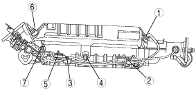
1
|
Tunnel member
|
|
2
|
Main silencer, presilencer
|
|
3
|
Exhaust gas pressure hose
|
|
4
|
Oxidation catalytic converter
|
|
5
|
A/F sensor
|
|
6
|
Exhaust gas temperature sensor
|
|
7
|
Turbocharger insulator No.1
|
|
8
|
Front pipe bracket No.1
|
|
9
|
Front pipe bracket No.2
|
|
10
|
Front pipe
|
|
11
|
Turbocharger insulator No.2
|
|
12
|
Oil pipe (supply)
|
|
13
|
Water pipe
|
|
14
|
Exhaust manifold insulator
|
|
15
|
Oil pipe (return)
|
|
16
|
Turbocharger bracket
|
|
17
|
Turbocharger
|
|
18
|
Exhaust manifold
|
Main Silencer, Presilencer Removal Note
1. Lower the rear crossmember. (See REAR CROSSMEMBER REMOVAL/INSTALLATION.)
2. Remove the main silencer, presilencer.
Oxidation Catalytic Converter Removal Note
1. Remove the A/F sensor, exhaust gas temperature sensor bracket installation bolts.
2. Disconnect the A/F sensor, exhaust gas temperature sensor connector.
3. Remove the oxidation catalytic converter
Water Pipe Removal Note
1. Drain the engine coolant before removing the water pipe. (See ENGINE COOLANT REPLACEMENT [MZR-CD (RF Turbo)].)
Turbocharger Removal Note
1. Remove the battery. (See BATTERY REMOVAL/INSTALLATION [MZR-CD (RF Turbo)].)
2. Remove the fuel filter component with the hose still connected. Position the fuel filter component so that it is out of the way. (R.H.D.) (See FUEL FILTER COMPONENT REMOVAL/INSTALLATION [MZR-CD (RF Turbo)].)
Exhaust Manifold Removal Note
1. Remove the EGR cooler before removing the exhaust manifold. (See EGR COOLER REMOVAL/INSTALLATION [MZR-CD (RF Turbo)].)
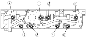
Exhaust Manifold Installation Note
1. Tighten the exhaust manifold installation nuts in the order shown.
2. Install the EGR cooler. (See EGR COOLER REMOVAL/INSTALLATION [MZR-CD (RF Turbo)].)
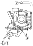
Water Pipe Installation Note
1. Tighten the water pipe installation nuts in the order shown.
2. Refill the engine coolant after Installing the water pipe. (See ENGINE COOLANT REPLACEMENT [MZR-CD (RF Turbo)].)
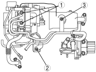
Oil Pipe (Supply) Installation Note
1. Tighten the oil pipe (supply) installation bolts in the order shown.
Front Pipe Installation Note
1. Tighten the bolts A.
2. Tighten the bolt B and nuts E.
3. Verify that brackets X, Y and Z are each properly installed.
4. Tighten the bolts C.
5. Tighten the bolts D.
-
Tightening torque
-
B, E: 22—29 N·m {2.3—2.9 kgf·m, 17—21 ft·lbf}
A, C, D: 38—51 N·m {3.9—5.2 kgf·m, 29—37 ft·lbf}
Exhaust Gas Temperature Sensor Installation Note
1. Remove the burn protection agent from the installation hole of the exhaust gas temperature sensor.
2. Apply the burn protection agent to the threads of the nuts and the exhaust gas temperature sensor, and tighten the sensor and nuts in the order shown in the figure.