 |
am3zzw00004260
INTAKE-AIR SYSTEM REMOVAL/INSTALLATION [MZR-CD (RF Turbo)]
id0113f1801900
MAF sensor
|
STEP |
ACTION |
PAGE/CONDITION |
|---|---|---|
|
1
|
Replace the MAF/IAT sensor.
|
–
|
|
2
|
Turn the engine switch on.
|
–
|
|
3
|
Perform mass air flow (MAF) sensor data reset procedure.
|
|
|
4
|
Start the engine.
|
Verify that the MIL dose not illuminate.
|
|
5
|
Turn the engine switch off.
|
–
|
|
6
|
Turn the engine switch on (Engine off).
|
–
|
|
7
|
Perform KOEO self-test procedure.
|
|
|
8
|
Turn the engine switch off.
|
–
|
|
9
|
Wait for 20 s.
|
–
|
|
10
|
Start the engine.
|
–
|
|
11
|
Perform KOER self-test procedure.
|
Warm up until the exhaust gas temperature (EXHTEMP1, EXHTEMP2, EXHTEMP3 PID) is 100 °C {212 °F} or more.
|
|
12
|
Turn the engine switch off.
|
–
|
Intake shutter valve
|
STEP |
ACTION |
PAGE/CONDITION |
|---|---|---|
|
1
|
Replace the intake shutter valve.
|
–
|
|
2
|
Turn the engine switch on.
|
–
|
|
3
|
Perform intake shutter valve/EGR valve data reset procedure.
|
–
|
|
4
|
Start the engine.
|
Verify that the MIL dose not illuminate.
|
|
5
|
Switch the ignition to off.
|
–
|
|
6
|
Switch the ignition to on (Engine off).
|
–
|
|
7
|
Perform KOEO self-test procedure.
|
|
|
8
|
Perform intake shutter valve/EGR valve initialization procedure.
|
Engine coolant temperature 60—95 °C {140—203 °F}.
|
|
9
|
Switch the ignition to off.
|
–
|
|
10
|
Wait for 20 s.
|
–
|
|
11
|
Start the engine.
|
–
|
|
12
|
Perform KOER self-test procedure.
|
Warm up until the exhaust gas temperature (EXHTEMP1, EXHTEMP2, EXHTEMP3 PID) is 100 °C {212 °F} or more.
|
|
13
|
Switch the ignition to off.
|
–
|
1. Disconnect the negative battery cable. (See СНЯТИЕ И УСТАНОВКА АККУМУЛЯТОРНОЙ БАТАРЕИ [MZR-CD (RF Turbo)].)
2. Remove the engine cover.
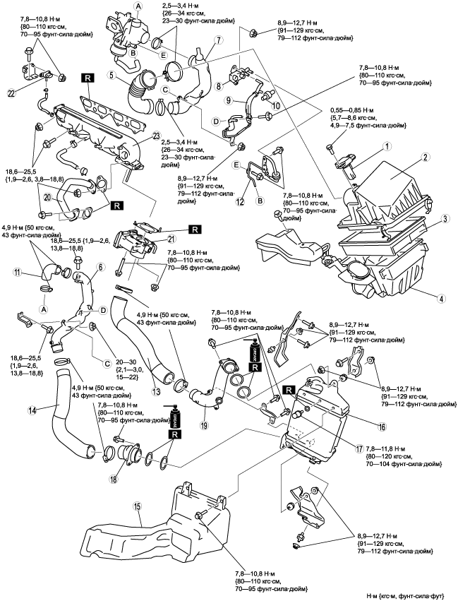
3. Remove in the order indicated in the table.
4. Install in the reverse order of removal.
am3zzw00004260
|
|
1
|
MAF/IAT sensor
|
|
2
|
Air cleaner cover
|
|
3
|
Air cleaner element
|
|
4
|
Air cleaner case
|
|
5
|
Air inlet hose
|
|
6
|
Turbocharger air outlet pipe
|
|
7
|
Air inlet pipe
|
|
8
|
VBC solenoid valve
|
|
9
|
Vacuum pipe
|
|
10
|
VBC check valve
|
|
11
|
Turbocharger air outlet hose No.1
|
|
12
|
VBC vacuum damper
|
|
13
|
Charge air cooler air outlet hose
|
|
14
|
Turbocharger air outlet hose No.2
|
|
15
|
Charge air cooler duct
|
|
16
|
Charge air cooler
|
|
17
|
IAT sensor No.2
|
|
18
|
Charge air cooler inlet pipe
|
|
19
|
Charge air cooler outlet pipe
|
|
20
|
EGR pipe
|
|
21
|
Intake shutter valve
|
|
22
|
Boost sensor
|
|
23
|
Intake manifold
(See Intake Manifold Removal Note.)
|
Turbocharger Air Outlet Pipe Removal Note
1. Remove the battery and the battery tray. (See СНЯТИЕ И УСТАНОВКА АККУМУЛЯТОРНОЙ БАТАРЕИ [MZR-CD (RF Turbo)].)
2. Remove the air inlet pipe fitting bolts.
3. Remove the turbocharger air outlet pipe.
Charge Air Cooler Duct Removal Note
1. Remove the front bumper before removing the charge air cooler duct. (See СНЯТИЕ И УСТАНОВКА ПЕРЕДНЕГО БАМПЕРА.)
Intake Shutter Valve Removal Note
1. Drain the engine coolant before removing the Intake shutter valve. (See ЗАМЕНА ОХЛАЖДАЮЩЕЙ ЖИДКОСТИ [MZR-CD (RF Turbo)].)
Intake Manifold Removal Note
1. Remove the supply pump, common rail and injection pipe before removing the intake manifold. (See СНЯТИЕ И УСТАНОВКА ТНВД [MZR-CD (RF Turbo)].)
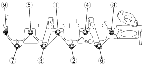
Intake Manifold Installation Note
1. Tighten the intake manifold installation bolts and nuts in the order shown.
am3zzw00004110
|
2. Install the supply pump, common rail and injection pipe. (See СНЯТИЕ И УСТАНОВКА ТНВД [MZR-CD (RF Turbo)].)
Intake Shutter Valve Installation Note
1. Refill the engine coolant after Installing the Intake shutter valve. (See ЗАМЕНА ОХЛАЖДАЮЩЕЙ ЖИДКОСТИ [MZR-CD (RF Turbo)].)
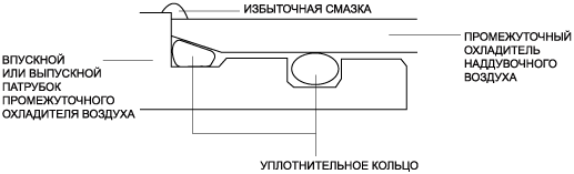
Charge Air Cooler Inlet Pipe, Charge Air Cooler Outlet Pipe Installation Note
1. Install a new O-ring to the charge air cooler inlet or outlet pipe.
2. Apply grease (RFY1 13569) along the perimeter of the installed O-ring.
am3zzw00004594
|
3. Install the charge air cooler inlet or outlet pipe to the charge air cooler.
4. Wipe away the excess grease.
am3zzw00004595
|
5. Verify that the charge air cooler inlet or outlet pipe is installed to the charge air cooler with no space between the two.
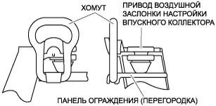
Air Cleaner Case Installation Note
1. Verify that two rubber mounts are installed on the battery support bracket.
2. Install the air cleaner case into the rubber mounts.
3. Using the strap, secure the shroud panel and the air cleaner case as shown in the figure.
am3zzw00004111
|