 |
am3zzw00004612
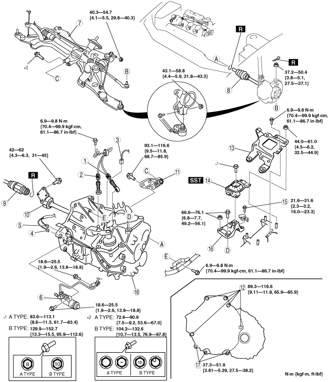
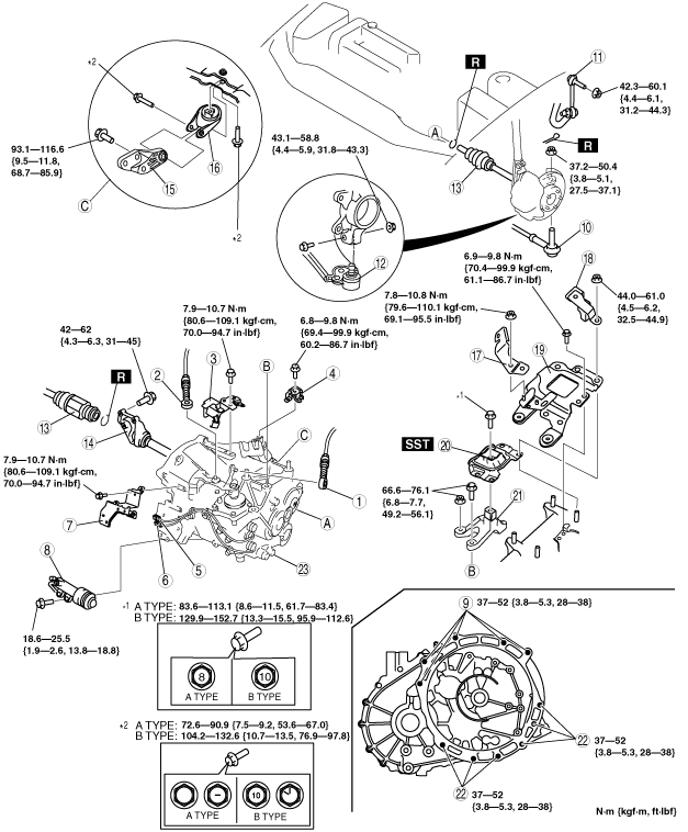
MANUAL TRANSAXLE REMOVAL/INSTALLATION [A26M-R]
id0515l1800600
L3 Turbo
1. Disconnect the negative battery cable.
2. Remove the battery and battery tray. (See BATTERY REMOVAL/INSTALLATION [L3 Turbo].)
3. Remove the air cleaner component. (See INTAKE-AIR SYSTEM REMOVAL/INSTALLATION [L3 Turbo].)
4. Remove the charge air cooler. (See INTAKE-AIR SYSTEM REMOVAL/INSTALLATION [L3 Turbo].)
5. Remove in the fuel pump resistor. (See FUEL PUMP RESISTOR REMOVAL/INSTALLATION [L3 Turbo].)
6. Remove the front wheels.
7. Remove the under cover and splash shields.
8. Remove the mudguard. (LF side)
9. Remove the starter. (See STARTER REMOVAL/INSTALLATION [L3 Turbo].)
10. Drain the transaxle oil into a suitable container.
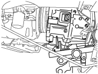
11. Remove in the order indicated in the figure.
12. Install in the reverse order of removal.
13. Add the specified amount of specified transaxle oil. (See TRANSAXLE OIL REPLACEMENT [A26M-R].)
am3zzw00004612
|
|
1
|
Selector cable
|
|
2
|
Shift cable
|
|
3
|
Wiring harness bracket
|
|
4
|
Cable bracket
|
|
5
|
Back-up light switch connector
|
|
6
|
Neutral switch connector
|
|
7
|
Wiring harness bracket
|
|
8
|
Clutch release cylinder
|
|
9
|
Transaxle mounting bolt (upper side)
|
|
10
|
Tie-rod end ball joint
|
|
11
|
Stabilizer control link
|
|
12
|
Lower arm ball joint
|
|
13
|
Drive shaft
|
|
14
|
Joint shaft
|
|
15
|
No.1 engine mount bracket
|
|
16
|
No.1 engine mount rubber
|
|
17
|
Wiring harness bracket
|
|
18
|
Dynamic damper
|
|
19
|
Battery tray bracket
|
|
20
|
No.4 engine mount rubber
|
|
21
|
No.4 engine mount bracket
|
|
22
|
Transaxle mounting bolt (lower side)
|
|
23
|
Manual transaxle
|
MZR-CD (RF Turbo)
1. Disconnect the negative battery cable.
2. Remove the following parts:
3. Drain the transaxle oil into a suitable container.
4. Remove in the order indicated in the table.
5. Install in the reverse order of removal.
6. Add the specified amount of specified transaxle oil.
7. Refill the engine coolant. (See ENGINE COOLANT REPLACEMENT [MZR-CD (RF Turbo)].)
am3zzw00004613
|
|
1
|
Selector cable
|
|
2
|
Shift cable
|
|
3
|
Crank angle sensor connector
|
|
4
|
Back-up light switch connector
|
|
5
|
Neutral switch connector
|
|
6
|
Clutch release cylinder
|
|
7
|
Front crossmember component, steering gear and linkage component
|
|
8
|
Drive shaft
|
|
9
|
Drive shaft
|
|
10
|
Joint shaft
|
|
11
|
No.1 engine mount bracket
|
|
12
|
Transaxle mounting bolt (upper side)
|
|
13
|
Battery tray bracket
|
|
14
|
No.4 engine mount rubber
|
|
15
|
Dynamic damper
|
|
16
|
No.4 engine mount bracket
|
|
17
|
Transaxle mounting bolt (lower side)
|
|
18
|
Manual transaxle
|
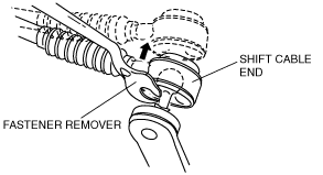
Shift Cable And Select Cable Removal Note
1. Remove the both shift cable end and select cable end using a fastener remover.
am3zzw00003734
|
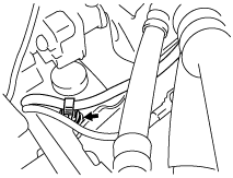
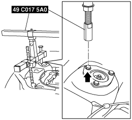
No.4 Engine Mount Removal Note
1. To install the front shaft (RH) of the SST (49 C017 5A0), remove the clip shown in the figure.
am3zzw00003735
|
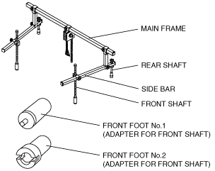
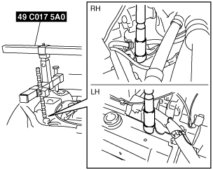
2. Install the SST using the following procedure.
am3zzw00003736
|
am3zzw00003737
|
am3zzw00003738
|
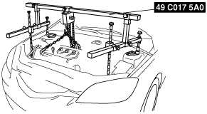
3. Support the engine using the SST.
am3zzw00003739
|
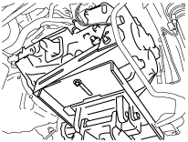
4. Remove the battery tray bracket, No.4 engine mount rubber and bracket.
Manual Transaxle Removal Note
1. Adjust the SST and lean the engine toward the transaxle.
am3zzw00003739
|
2. Support the transaxle on a jack.
am3zzw00003741
|
3. Remove the transaxle mounting bolts.
4. Remove the transaxle.
Manual Transaxle Installation Note
1. Set the transaxle on a jack and lift into place.
am3zzw00005005
|
2. Install the transaxle mounting bolts.
3. Adjust the SST (49 C017 5A0) so that the engine is located at the specified position.
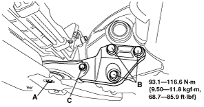
No.1 Engine Mount and No.4 Engine Mount Installation Note
1. Install the No.1 engine mount bracket to the transaxle.
2. Install the No.1 engine mount rubber.
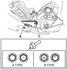
3. Tighten the bolts B, and then temporarily tighten the bolt A and C. (L3 Turbo)
4. Tighten the bolts B, and then temporarily tighten the bolt C. (MZR-CD (RF Turbo))
am3zzw00003743
|
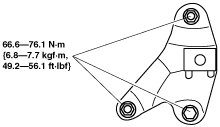
5. Install the No.4 engine mount bracket on the transaxle case and tighten bolt and nuts.
L3 Turbo
am3zzw00003744
|
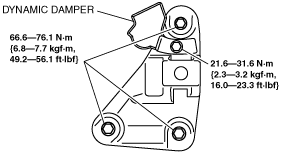
MZR-CD (RF Turbo)
am3zzw00003788
|
6. Install the dynamic damper. (MZR-CD (RF Turbo))
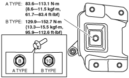
7. Place the No.4 engine mount rubber with the body stud bolts passing through the holes and tighten the bolt as shown in the figure.
am3zzw00004614
|
8. Place the battery tray bracket over the No.4 engine mount bracket with the body stud bolts passing through the holes.
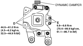
9. Place the dynamic damper over the battery tray bracket with the body stud bolts passing through the holes, then tighten the bolts and nuts in the order of D, E. (L3 Turbo)
am3zzw00004544
|
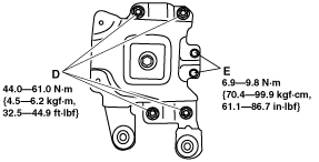
10. Tighten the bolts and nuts in the order of D, E. (MZR-CD (RF Turbo))
am3zzw00004545
|
11. Remove the SST (49 C017 5A0).
12. Install the clip as shown in the figure.
am3zzw00003735
|
13. Fully tighten the bolts in the order of A, C.
am3uuw00006452
|