TIMING BELT REMOVAL/INSTALLATION [MZR-CD (RF Turbo)]
id0110f1804000
-
Warning
-
• Fuel vapor is hazardous. It can very easily ignite, causing serious injury and damage. Always keep sparks and flames away from fuel.
• Fuel line spills and leakage are dangerous. Fuel can ignite and cause serious injures or death and damage. Fuel can also irritate skin and eyes. To prevent this, always complete the “Fuel Line Safety Procedure”. (See
BEFORE SERVICE PRECAUTION [MZR-CD (RF Turbo)].)
1. Disconnect the negative battery cable.
2. Remove the front tire (RH).
3. Remove the under cover and both splash shield as a single unit.
4. Position the coolant reserve tank so that it is out of the way. (See COOLANT RESERVE TANK REMOVAL/INSTALLATION [MZR-CD (RF Turbo)].)
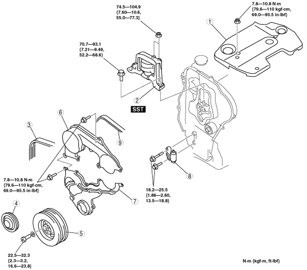
5. Remove in the order shown in the table.
6. Install in the reverse order of removal.
7. Start the engine and inspect the pulleys and the drive belt for runout and contact.
|
1
|
Engine cover
|
|
2
|
No.3 engine joint bracket
|
|
3
|
Drive belt
|
|
4
|
Crankshaft pulley cover
|
|
5
|
Crankshaft pulley
|
|
6
|
Upper timing belt cover
|
|
7
|
Lower timing belt cover
|
|
8
|
Timing belt auto tensioner
|
|
9
|
Timing belt
|
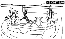
No.3 Engine Joint Bracket Removal Note
1. Remove the air cleaner assembly. (See INTAKE-AIR SYSTEM REMOVAL/INSTALLATION [MZR-CD (RF Turbo)].)
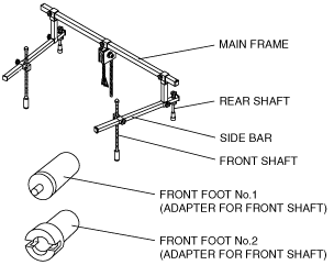
2. Install the SST using the following procedure.
-
Caution
-
• Refer to the SST instruction manual for the basic handing procedure.
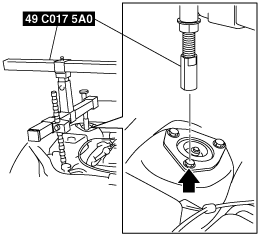
- (1) Install the right rear shaft of the SST to the bolt of the right shock absorber as shown in the figure.
-
- (2) Install the left rear shaft of the SST to the bolt of the left shock absorber (Identical position to right side).
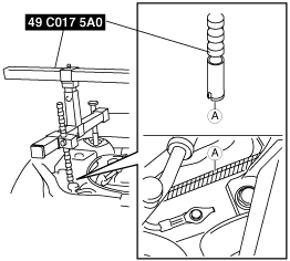
- (3) Install front foot No.2 to the right front shaft of the SST, then align the groove of the right front shaft of the SST with the folded up part of the vehicle as shown in the figure.
-
- (4) Install front foot No.2 to the left front shaft of the SST, then align the groove of the left front shaft of the SST with the folded up part of the vehicle frame (Identical position to right side).
- (5) Adjust the positions of the SST side bars so that they are the same height (left and right) and horizontal.
- (6) Make sure each joint is securely tightened.
3. Suspend the engine using the SST.
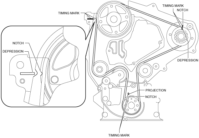
Timing Belt, Timing Belt Auto Tensioner Removal Note
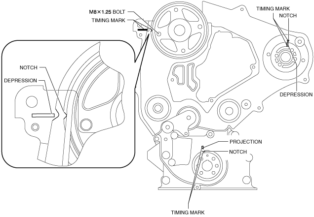
1. Turn the crankshaft clockwise and align the timing marks as shown.
-
Caution
-
• Forcefully twisting the belt, turning it inside out, or allowing oil or grease on it will damage the belt and shorten its life.
• After removing the timing belt, do not move the crankshaft and/or camshaft from this position because it can cause the valve and piston to come into contact.
2. Remove the timing belt auto tensioner.
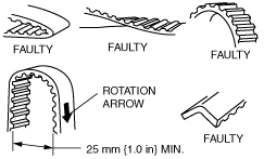
3. Mark the timing belt rotation on the belt for proper reinstallation.
Timing Belt, Timing Belt Auto Tensioner Installation Note
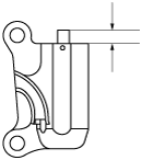
1. Measure the tensioned rod projection length.
-
• If not as specified, replace the timing belt auto tensioner.
-
Projection (free length)
-
12.9—14.6 mm {0.508—0.574 in}
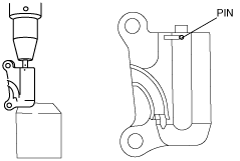
2. Inspect the timing belt auto tensioner for oil leakage.
-
• If not as specified, replace the timing belt auto tensioner.
-
Caution
-
• Placing the timing belt auto tensioner horizontally can cause oil leakage and damage the timing belt auto tensioner. Place the timing belt auto tensioner vertically when using a vise.
3. Verify the thrust of the timing belt auto tensioner rod in the following order:
-
• If the timing belt auto tensioner rod is rigid when it is pushed with a force of approximately 235 N {24 kgf, 53 Ibf}, push it down slowly and fix the pin in the hole.
• If there is no resistance on the timing belt auto tensioner rod and it moves slightly when it is pushed with a force of approximately 235 N {24 kgf, 53 Ibf};
- (1) Push it down slowly two or three times to the bottom end of the rod.
- (2) If the rod protrudes approximately 8.1 mm {0.32 in}, verify that there is resistance on the timing belt auto tensioner rod.
-
-
Caution
-
• To prevent damage to the inside of the timing belt auto tensioner, do not press down the timing belt auto tensioner rod with a force greater than the specified 235 N {24 kgf, 53 lbf}.
Be careful that the rod does not touch the bottom.
-
• If the timing belt auto tensioner rod projection is restored, push it down slowly and fix the pin in the hole.
-
― If the resistance is not restored, replace the timing belt auto tensioner.
-
Caution
-
• To prevent the bolts from damaging the fuel injection pump and pulley, do not fully tighten the fixing bolts. If it contacts the pulley surface, it will damage the pulley.
4. Verify that all timing marks are correctly aligned.
-
• If not, align all timing marks according to the procedure below.
5. Fix the camshaft pulley to the cylinder head using bolt (M8 x1.25).
-
Caution
-
• Turn the crankshaft in the direction which will prevent the TDC and BDC from being passed. Otherwise it can cause the valve and piston to come into contact.
- (1) Turn the crankshaft and set it at an angle of 45° or more away from the TDC and BDC.
- (2) Align the timing marks of the camshaft pulley.
- (3) Align the timing marks of the supply pump pulley.
- (4) Turn the crankshaft and align the timing marks of the timing belt pulley.
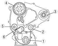
6. Install the timing belt on the pulleys in the order shown below.
- (1) Timing belt pulley
- (2) Idler
- (3) Supply pump pulley
- (4) Camshaft pulley
- (5) Water pump pulley
- (6) Tensioner pulley
-
7. Remove the camshaft pulley fixing bolt.
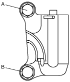
8. Hand tighten the timing belt auto tensioner bolts in the order A to B as indicated in the figure.
9. Tighten the timing belt auto tensioner bolts in the order A to B as indicated in the figure.
-
Tightening torque
-
18.2—25.5 N·m {1.86—2.60 kgf·m, 13.5—18.8 ft·lbf}
10. Remove the pin from the timing belt auto tensioner to apply tension to the belt.
11. Turn the crankshaft clockwise twice, and align the timing marks.
12. Verify that all timing marks are correctly aligned.
-
• If not as specified, repeat from Timing Belt, Timing Belt Auto Tensioner Removal Note.
Crankshaft Pulley Installation Note
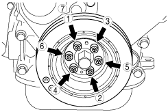
1. Tighten the bolts in the order shown.
-
Tightening torque
-
22.5—32.3 N·m {2.3—3.2 kgf·m, 16.6—23.8 ft·lbf}
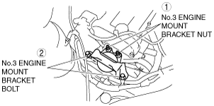
No.3 Engine Joint Bracket Installation Note
1. Tighten the No.3 engine joint bracket bolts and nuts in the order as shown in the figure.
-
Tightening torque
-
(1) 74.5—104.9 N·m {7.60—10.6 kgf·m, 55.0—77.3 ft·lbf}
(2) 70.7—93.1 N·m {7.21—9.49 kgf·m, 52.2—68.6 ft·lbf}