 |
am3zzw00004974
MANUAL TRANSAXLE REMOVAL/INSTALLATION [J65M-R]
id0515c1800600
1. Remove the following parts:
2. Drain the transaxle oil into a suitable container.
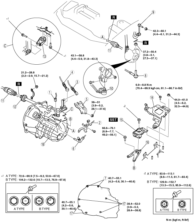
3. Remove in the order indicated in the table.
4. Install in the reverse order of removal.
5. Add the specified amount of specified transaxle oil.
6. Perform the clutch fluid line air bleeding. (See CLUTCH FLUID AIR BLEEDING/REPLACEMENT.)
am3zzw00004974
|
|
1
|
Back-up light switch connector
|
|
2
|
Harness bracket
|
|
3
|
Select cable
|
|
4
|
Shift cable
|
|
5
|
Cable bracket
|
|
6
|
Clutch pipe connector
|
|
7
|
Transaxle mounting bolt (upper side)
|
|
8
|
Tie-rod end ball joint
|
|
9
|
Stabilizer control link
|
|
10
|
Lower arm ball joint
|
|
11
|
Drive shaft
|
|
12
|
Joint shaft
|
|
13
|
No.1 engine mount rubber
|
|
14
|
Battery tray bracket
|
|
15
|
No.4 engine mount rubber
|
|
16
|
No.4 engine mount bracket
|
|
17
|
Transaxle mounting bolt (lower side)
|
|
18
|
Manual transaxle
|
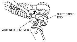
Shift Cable And Select Cable Removal Note
1. Remove both the shift cable end and select cable end using a fastener remover.
am3zzw00004975
|
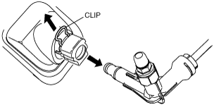
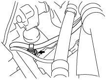
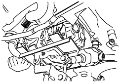
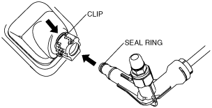
Clutch Pipe Connector Removal Note
1. Pull the clutch release cylinder clip to the position shown in the figure and pull the clutch pipe connector straight out to detach.
am3zzw00004976
|
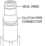
2. Verify that the seal ring is removed together with the clutch pipe connector.
am3zzw00009116
|
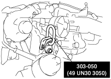
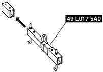
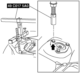
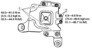
No.4 Engine Mount Removal Note
1. Use the bolt to install the SST to the position shown in the figure.
am3zzw00004977
|
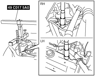
2. To install the front shaft (RH) of the SST (49 C017 5A0), remove the clip shown in the figure.
am3zzw00004978
|
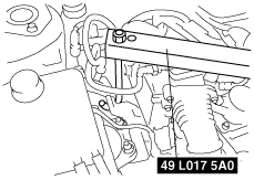
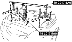
3. Set the SST as shown in the figure.
am3zzw00004979
|
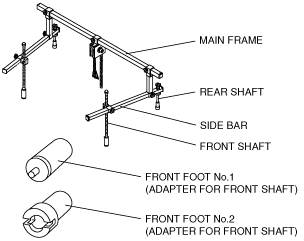
4. Set the SST as shown in the figure.
am3zzw00004980
|
5. Install the SST using the following procedure.
am3zzw00004981
|
am3zzw00004982
|
am3zzw00004983
|
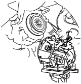
6. Support the engine using the SST.
am3zzw00004984
|
7. Remove the battery tray bracket, No.4 engine mount rubber and bracket.
Manual Transaxle Removal Note
1. Adjust the SST and lean the engine toward the transaxle.
am3zzw00004984
|
2. Support the transaxle on a jack.
am3zzw00004985
|
3. Remove the transaxle mounting bolts.
4. Remove the transaxle.
Manual Transaxle Installation Note
1. Set the transaxle on a jack and lift into place.
am3zzw00004986
|
2. Install the transaxle mounting bolts.
3. Adjust the SST (49 C017 5A0) so that the engine is located at the specified position.
No.1 Engine Mount and No.4 Engine Mount Installation Note
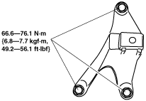
1. Install the No.4 engine mount bracket on the transaxle case and tighten bolt and nuts.
am3zzw00004987
|
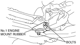
2. Install the No.1 engine mount rubber to the cross member and temporarily tighten bolts.
am3zzw00004988
|
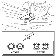
3. Place the No.4 engine mount rubber with the body stud bolts passing through the holes and tighten a bolt shown in the figure.
am3zzw00004989
|
4. Place the battery tray bracket on the No.4 engine mount rubber with body stud bolts passing through the holes and tighten bolts and nuts in the order as shown in the figure.
am3zzw00004990
|
5. Remove the SSTs.
6. Install the clip as shown in the figure.
am3zzw00004978
|
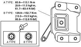
7. Fully tighten the bolts.
am3zzw00004991
|
Clutch Pipe Connector Installation Note
1. Verify that the seal ring is installed to the groove at the end of the clutch pipe connector.
am3zzw00009116
|
2. Return the clutch master cylinder clip to the position shown in the figure.
am3zzw00004992
|
3. Insert the clutch pipe connector straight.
4. Pull the clutch pipe connector to verify that it does not come off and then reinsert completely.