 |
am3zzw00004057
PCM REMOVAL/INSTALLATION [MZR-CD (RF Turbo)]
id0140f1802400
|
STEP |
ACTION |
PAGE/CONDITION |
|---|---|---|
|
1
|
Perform diesel particulate filter regeneration procedure.
|
|
|
2
|
Read the PCM configuration data.
|
|
|
3
|
Replace the PCM.
|
|
|
4
|
Turn the engine switch on.
|
–
|
|
5
|
Write the PCM configuration data.
|
–
|
|
6
|
Perform A/F sensor date reset procedure.
|
|
|
7
|
Perform IMMOBILIZER SYSTEM programming.
|
|
|
8
|
Perform after repair procedure.
|
|
|
9
|
Turn the engine switch off.
|
–
|
|
10
|
Wait for 20 s.
|
–
|
|
11
|
Start the engine.
|
Verify that the MIL does not illuminate.
|
|
12
|
Turn the engine switch off.
|
–
|
|
13
|
Turn the engine switch on (Engine off).
|
–
|
|
14
|
Perform KOEO self-test procedure.
|
|
|
15
|
Perform Intake shutter valve/EGR valve initialization procedure.
|
|
|
16
|
Perform diesel particulate filter reset procedure.
|
|
|
17
|
Turn the engine switch off.
|
–
|
|
18
|
Wait for 20 s.
|
–
|
|
19
|
Start the engine.
|
–
|
|
20
|
Perform KOER self-test procedure.
|
Warm up until the exhaust gas temperature (EXHTEMP1, EXHTEMP2, EXHTEMP3 PID) is 100 °C {212 °F} or more.
|
|
21
|
Perform injection amount correction procedure.
|
Engine coolant temperature 65—95 °C {149—203 °F}.
Intake air temperature 15—65 °C {59—149 °F}.
Fuel temperature 30—60 °C {86—140 °F}.
|
|
22
|
Turn the engine switch off.
|
–
|
|
23
|
Wait for 20 s.
|
–
|
|
24
|
Start the engine.
|
–
|
|
25
|
Perform diesel particulate filter assessment procedure.
|
Engine coolant temperature 60 °C {140 °F} or more.
|
|
26
|
Perform diesel particulate filter regeneration.
|
|
|
27
|
Perform repair verification drive mode.
|
|
|
28
|
Verify that O2S11_CAL value is not 0 using the PID O2S11_CAL.
― If the value is 0, return to the previous step.
|
|
|
29
|
Turn the engine switch off.
|
–
|
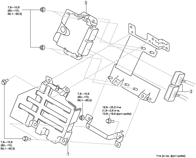
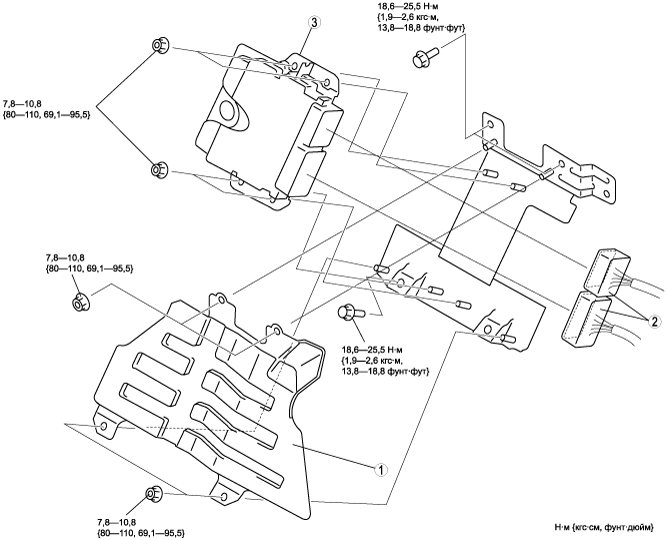
European (L.H.D.) specs.
1. Disconnect the negative battery cable.
2. Remove the front side trim (right-side). (See СНЯТИЕ И УСТАНОВКА ОБИВКИ ПЕРЕДНЕЙ ЧАСТИ ПОРОГА.)
3. Partially peek back the floor covering.
4. Remove in the order indicated in the table.
am3zzw00004057
|
|
1
|
PCM cover
|
|
2
|
PCM connector
|
|
3
|
PCM
|
5. Install in the reverse order of removal.
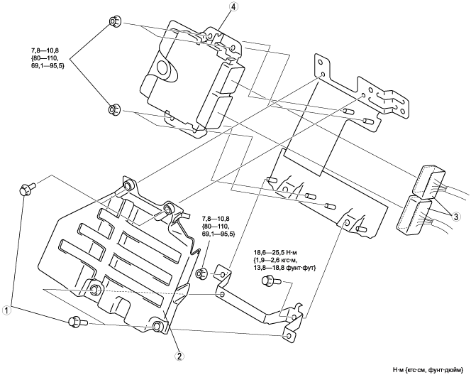
U.K. Specs.
1. Disconnect the negative battery cable.
2. Remove the front side trim (left-side). (See СНЯТИЕ И УСТАНОВКА ОБИВКИ ПЕРЕДНЕЙ ЧАСТИ ПОРОГА.)
3. Partially peek back the floor covering.
4. Remove in the order indicated in the table.
am3zzw00004058
|
|
1
|
Set bolt
(See Set bolt removal note.)
(See Set bolt installation note.)
|
|
2
|
PCM cover
|
|
3
|
PCM connector
|
|
4
|
PCM
|
5. Install in the reverse order of removal.
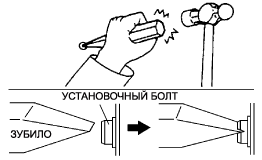
Set bolt removal note
1. Using a chisel and a hammer, cut a groove on the head of the set bolt so that a screwdriver can be inserted.
2. Loose the set bolt using an impact screwdriver or pliers.
am3zzw00004059
|
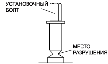
Set bolt installation note
1. Install a new set bolt and tighten it until the neck of the bolt is cut.
am3zzw00004060
|
Australian specs.
1. Disconnect the negative battery cable.
2. Remove the front side trim (left-side). (See СНЯТИЕ И УСТАНОВКА ОБИВКИ ПЕРЕДНЕЙ ЧАСТИ ПОРОГА.)
3. Partially peek back the floor covering.
4. Remove in the order indicated in the table.
am3zzw00004578
|
|
1
|
PCM cover
|
|
2
|
PCM connector
|
|
3
|
PCM
|
5. Install in the reverse order of removal.