 |
am3uuw00000151
ON-BOARD DIAGNOSTIC TEST [MZR-CD (RF Turbo)]
id0102f1801000
DTC Reading Procedure
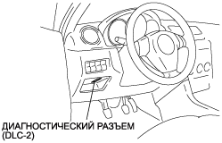
1. Connect the M-MDS to the DLC-2.
am3uuw00000151
|
2. After the vehicle is identified, select the following items from the initial screen of the M-MDS.
3. Then, select the “Retrieve CMDTCs” and perform procedures according to directions on the M-MDS screen.
4. Verify the DTC according to the directions on the M-MDS screen.
5. After completion of repairs, clear all DTCs stored in the PCM, while referring to “AFTER REPAIR PROCEDURE“.
Pending Trouble Code Access Procedure
1. Connect the M-MDS to the DLC-2.
am3uuw00000151
|
2. After the vehicle is identified, select the following items from the initial screen of the M-MDS.
3. Then, select the “Retrieve CMDTCs” and perform procedures according to directions on the M-MDS screen.
4. Retrieve the pending trouble codes according to the directions on the M-MDS screen.
Freeze Frame PID Data Access Procedure
1. Connect the M-MDS to the DLC-2.
am3uuw00000151
|
2. After the vehicle is identified, select the following items from the initial screen of the M-MDS.
3. Then, select the “Retrieve CMDTCs” and perform procedures according to directions on the M-MDS screen.
4. Retrieve the freeze frame PID data according to the directions on the M-MDS screen.
PID/DATA Monitor And Record Procedure
1. Connect the M-MDS to the DLC-2.
am3uuw00000151
|
2. After the vehicle is identified, select the following items from the initial screen of the M-MDS.
3. Select the PID from the PID table.
4. Verify the PID data according to the directions on the M-MDS screen.
Simulation Function Procedure
1. Connect the M-MDS to the DLC-2.
am3uuw00000151
|
2. After the vehicle is identified, select the following items from the initial screen of the M-MDS.
3. Select the simulation items from the PID table.
4. Perform the simulation function, inspect the operations for each parts.