CYLINDER HEAD GASKET REPLACEMENT [MZR-CD (RF Turbo)]
id0110f1800700
-
Warning
-
• Fuel vapor is hazardous. It can very easily ignite, causing serious injury and damage. Always keep sparks and flames away from fuel.
• Fuel line spills and leakage are dangerous. Fuel can ignite and cause serious injuries or death and damage. Fuel can also irritate skin and eyes. To prevent this, always complete the “Fuel Line Safety Procedure”. (See
BEFORE SERVICE PRECAUTION [MZR-CD (RF Turbo)].)
1. Remove the timing belt. (See TIMING BELT REMOVAL/INSTALLATION [MZR-CD (RF Turbo)].)
2. Remove the battery and tray. (See BATTERY REMOVAL/INSTALLATION [MZR-CD (RF Turbo)].)
3. Drain the engine coolant. (See ENGINE COOLANT REPLACEMENT [MZR-CD (RF Turbo)].)
4. Remove the vacuum pump. (See VACUUM PUMP REMOVAL/INSTALLATION [MZR-CD (RF Turbo)].)
5. Remove the P/S oil pump with the oil hose still connected. Position the P/S oil pump so that it is out of the way. Use wire or rope to secure. (See POWER STEERING OIL PUMP REMOVAL/INSTALLATION [MZR-CD (RF Turbo)].)
6. Remove the turbocharger. (See EXHAUST SYSTEM REMOVAL/INSTALLATION [MZR-CD (RF Turbo)].)
7. Remove all the glow plugs. (See GLOW PLUG REMOVAL/INSTALLATION [MZR-CD (RF Turbo)].)
8. Remove the radiator upper hose. (See RADIATOR REMOVAL/INSTALLATION [MZR-CD (RF Turbo)].)
9. Remove the EGR valve. (See EGR VALVE REMOVAL/INSTALLATION [MZR-CD (RF Turbo)].)
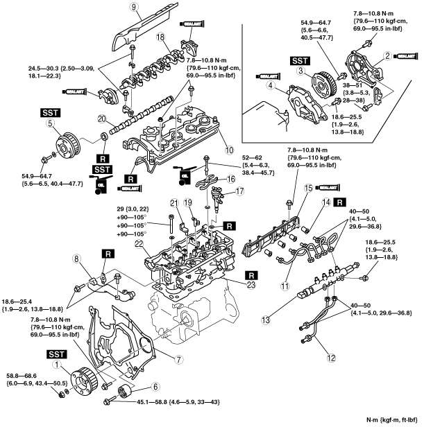
10. Remove in the order shown in the table.
11. Install in the reverse order of removal.
12. Refill the engine coolant. (See ENGINE COOLANT REPLACEMENT [MZR-CD (RF Turbo)].)
13. Inspect valve clearance. (See VALVE CLEARANCE INSPECTION [MZR-CD (RF Turbo)].)
14. Inspect the engine oil level.
-
15. Inspect the compression. (See COMPRESSION INSPECTION [MZR-CD (RF Turbo)].)
16. Start the engine and:
- (1) Inspect the pulleys and the drive belt for runout and contact.
- (2) Inspect the engine oil, engine coolant, and fuel leakage.
- (3) Inspect the idle speed. (See ENGINE TUNE-UP [MZR-CD (RF Turbo)].)
-
|
1
|
Supply pump pulley
|
|
2
|
Gear cover
|
|
3
|
Drive gear
|
|
4
|
Gear case
|
|
5
|
Camshaft pulley
|
|
6
|
Idler
|
|
7
|
Seal plate
|
|
8
|
Water outlet
|
|
9
|
Insulator
|
|
10
|
Cylinder head cover
|
|
11
|
Fuel Injection pipe (Fuel injector side)
|
|
12
|
Fuel Injection pipe (Fuel supply pump side)
|
|
13
|
Common rail
|
|
14
|
Nozzle seal
|
|
15
|
Side wall
|
|
16
|
Fuel injector bracket
|
|
17
|
Fuel injector
|
|
18
|
Rocker arm and rocker arm shaft
|
|
19
|
Rocker bridge
|
|
20
|
Camshaft
|
|
21
|
Breather pipe
|
|
22
|
Cylinder head
|
|
23
|
Cylinder head gasket
|
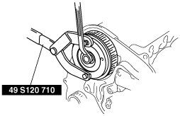
Supply Pump Pulley Removal Note
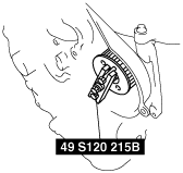
1. Hold the supply pump pulley using the SST and remove the supply pump pulley lock nut.
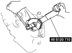
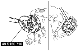
2. Separate the supply pump pulley from the supply pump shaft using the SST.
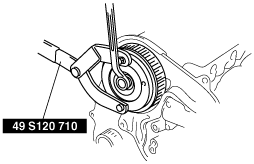
Drive Gear Removal Note
1. Hold the camshaft using the SST.
2. Remove the drive gear lock bolt.
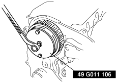
Camshaft Pulley Removal Note
1. Hold the camshaft using the SST.
2. Remove the camshaft pulley lock bolt.
3. Remove the camshaft pulley using the SST.
Seal Plate Removal Note
1. Remove the seal plate from the engine component. However, the seal plate cannot be removed completely. Separate the seal plate from the engine component by removing the fitting bolts so that the cylinder head can be removed.
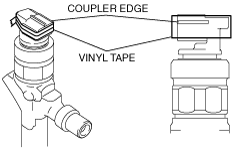
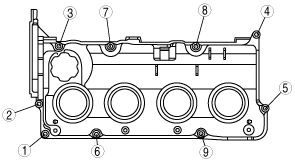
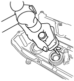
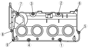
Cylinder Head Cover Removal Note
1. Wrap the fuel injector coupler with vinyl tape 2 times covering the coupler edge so as not to damage the injector seal.
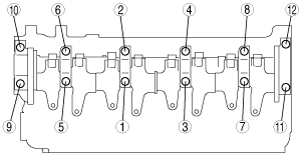
2. Loosen the bolts in the order shown in the figure.
3. Remove the cylinder head cover carefully so as not to damage the injector seal from coupler edge.
4. Verify that there are no cracks or rips on the injector seal.
5. If there are any cracks or rips, remove the injector seal using the following procedure to replace it with a new one.
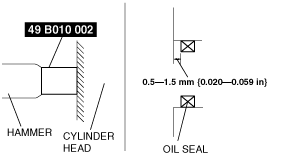
- (1) Being careful not to damage the cylinder head cover, carefully remove the injector seal, lightly tapping it from the back side of the cylinder head cover with a flathead screwdriver.
-
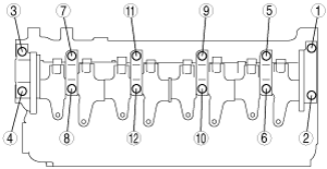
Rocker Arm and Rocker Arm Shaft Removal Note
1. Loosen the bolts in two or three steps in the order shown.
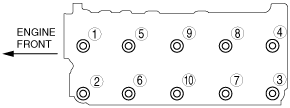
Cylinder Head Removal Note
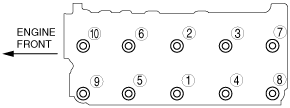
1. Loosen the cylinder head bolts in two or three steps in the order shown.
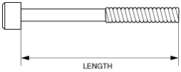
Cylinder Head Installation Note
1. Measure the length of each cylinder head bolt.
-
• Replace any that exceeds maximum length.
-
Cylinder head bolt length
-
Standard : 159.7—160.3 mm {6.288—6.311 in}
Maximum : 161.0 mm {6.338 in}
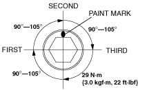
2. Tighten the bolts in two or three steps in the order shown.
-
Tightening torque
-
29 N·m {3.0 kgf·m, 22 ft·lbf}
3. Put a paint mark on each bolt head.
4. Using the marks as a reference, tighten the bolts by turning each 90°—105° in the sequence shown.
5. Further tighten each bolt by turning another 90°—105°.
6. Then further tighten each bolt by turning another 90°—105°.
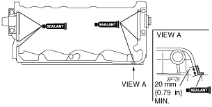
Rocker Arm and Rocker Arm Shaft Installation Note
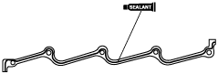
1. Apply sealant as shown in the figure.
-
Thickness
-
2 mm {0.079 in}
2. Install the camshaft caps according to the cap number.
3. Install the rocker arm shaft plane side upward.
-
Caution
-
• Because there is little camshaft thrust clearance, the camshaft must be held horizontally while it is installed. Otherwise, excessive force will be applied to the thrust area, causing burrs on the thrust receiving area of the cylinder head journal. To avoid this, the following procedure must be observed.
4. Tighten the bolts in two or three steps in the order shown.
-
Tightening torque
-
24.5—30.3 N·m {2.50—3.09 kgf·m, 18.1—22.3 ft·lbf}
5. Apply clean engine oil to the new oil seal.
6. Push the oil seal slightly in by hand.
7. Tap the oil seal into the cylinder head using the SST and a hammer.
-
Pushing distance of the camshaft oil seal (from the edge of the cylinder head)
-
0.5—1.5 mm {0.020—0.059 in}
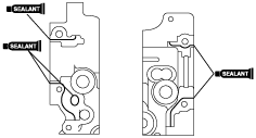
Side Wall Installation Note
1. Apply silicone sealant as shown in the figure.
-
Thickness
-
2 mm {0.079 in}
Fuel Injection Pipe Installation Note
-
Caution
-
• Fuel injection pipes can be removed and reinstalled up to five times. If removing them for the sixth time, be sure to replace them with new ones.
Cylinder Head Cover Installation Note
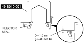
1. Press in the injector seal using the SST and a hammer.
-
Injector seal press-in amount
-
0—1.5 mm {0—0.059 in}
2. Wrap the fuel injector coupler with vinyl tape 2 times covering the coupler edge so as not to damage the injector seal.
3. Apply silicone sealant to the shaded areas.
-
Thickness
-
2 mm {0.079 in}
4. Install the cylinder head cover so as not to damage the injector seal from the coupler edge.
5. Verify that the injector seal is not damaged, then remove the vinyl tape wrapped around the fuel injector coupler.
6. Tighten the bolts in the order shown.
-
Tightening torque
-
7.8—10.8 N·m {79.6—110 kgf·cm, 69.0—95.5 in·lbf}
Water Outlet Installation Note
1. Tighten the bolts in the order shown.
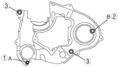
Seal Plate Installation Note
1. Install the seal plate and hand tighten the bolt in the order A to B.
2. Tighten the bolts in the order shown.
-
Tightening torque
-
7.8—10.8 N·m {79.6—110 kgf·cm, 69.0—95.5 in·lbf}
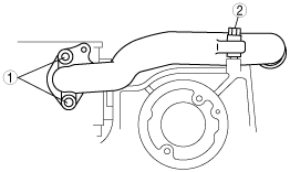
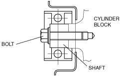
Idler Installation Note
-
Caution
-
• The idler has a front and back relative to the engine, therefore when installing make sure that the longer projection of the shaft is on the engine side as indicated in the figure.
Camshaft Pulley Installation Note
1. Hold the camshaft using the SST.
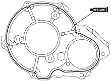
Gear Case Installation Note
1. Apply silicone sealant as shown in the figure.
-
Thickness
-
1.5—2.5 mm {0.060—0.098 in}
2. Tighten the bolts in clockwise order.
Drive Gear Installation Note
1. Hold the camshaft using the SST.
2. Tighten the drive gear lock bolt.
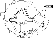
Gear Cover Installation Note
1. Apply silicone sealant as shown in the figure.
-
Thickness
-
1.5—2.5 mm {0.060—0.098 in}
2. Tighten the bolts in clockwise order.
Supply Pump Pulley Installation Note
1. Hold the supply pump pulley using the SST and install the the supply pump pulley lock nut.
-
Tightening torque
-
58.8—68.6 N·m {6.0—6.9 kgf·m, 43.4—50.5 ft·lbf}