VALVE CLEARANCE ADJUSTMENT [MZR-CD (RF Turbo)]
id0110f1803300
1. Remove the engine cover. (See TIMING BELT REMOVAL/INSTALLATION [MZR-CD (RF Turbo)].)
2. Remove the timing belt cover bolt as shown.
3. Remove the cylinder head cover. (See CYLINDER HEAD GASKET REPLACEMENT [MZR-CD (RF Turbo)].)
4. Turn the crankshaft and align the timing mark so that the piston of the No.1 or No.4 cylinder is at TDC of compression.
5. Remove the fuel injector. (See FUEL INJECTOR REMOVAL/INSTALLATION [MZR-CD (RF Turbo)].)
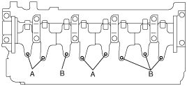
6. Adjust the valve clearance A with the No.1 cylinder at TDC of compression, and those of B with the No.4 cylinder at TDC of compression.
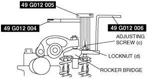
- (1) Hold the rocker bridge using the SST (49 G012 006).
- (2) Loosen the locknut (d) using the SST (49 G012 004), and then turn the adjusting screw (c) using the SST (49 G012 005) until it is separated from the valve stem completely.
-
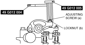
- (3) Loosen the rocker arm locknut (b) using the SST (49 G012 004), and then turn the adjusting screw (a) using the SST (49 G012 005) until it is separated from the rocker bridge completely.
-
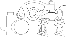
- (4) Insert a feeler gauge between the rocker arm and rocker bridge (e).
-
-
Standard valve clearance [Engine cold]
-
IN: 0.09—0.21 mm {0.004—0.008 in}
EX: 0.29—0.41 mm {0.012—0.016 in}
- (5) Adjust the valve clearance by turning the adjuster (a) using the SST (49 G012 005).
- (6) Temporarily tighten locknut (b) using the SST (49 G012 004).
- (7) With the feeler gauge inserted between the rocker arm and rocker bridge, verify that the feeler gauge remains firmly in place even when the adjusting screw (c) is loosened.
-
-
• If the feeler gauge does not remain firmly in place, repeat procedures from Step 1.
- (8) Turn the adjusting screw (c) using the SST (49 G012 005) until it reaches the valve stem and the feeler gauge fits more firmly. Then tighten the locknut (d) using the SST (49 G012 004) to specified torque.
-
-
Tightening torque
-
16—20 N·m {1.6—2.1 kgf·m, 12—15 ft·lbf}
- (9) Loosen the locknut (b) using the SST (49 G012 004) and readjust the valve clearance (e).
-
-
Standard valve clearance [Engine cold]
-
IN: 0.09—0.21 mm {0.004—0.008 in}
EX: 0.29—0.41 mm {0.012—0.016 in}
- (10) Tighten the locknut (b) using the SST (49 G012 004) to specified torque.
-
-
Tightening torque
-
16—20 N·m {1.6—2.1 kgf·m, 12—15 ft·lbf}
- (11) Verify the valve clearance at (e).
-
-
Standard valve clearance [Engine cold]
-
IN: 0.09—0.21 mm {0.004—0.008 in}
EX: 0.29—0.41 mm {0.012—0.016 in}
7. Turn the crankshaft one full turn and adjust the remaining valve clearances.
8. Install the fuel injector. (See FUEL INJECTOR REMOVAL/INSTALLATION [MZR-CD (RF Turbo)].)
9. Install the cylinder head cover. (See CYLINDER HEAD GASKET REPLACEMENT [MZR-CD (RF Turbo)].)
10. Install the timing belt cover bolt as shown.
-
Tightening torque
-
7.8—10.8 N·m {79.6—110 kgf·cm, 69.0—95.5 in·lbf}
11. Install the engine cover. (See TIMING BELT REMOVAL/INSTALLATION [MZR-CD (RF Turbo)].)