|
am3zzw00004604
MANUAL TRANSAXLE REMOVAL/INSTALLATION [F35M-R]
id0515a1800600
1. Remove the following parts:
2. Disconnect the vehicle speed sensor connector.(without ABS)
3. Drain the transaxle oil into a suitable container.
4. Remove in the order indicated in the table.
5. Install in the reverse order of removal.
6. Add the specified amount of specified transaxle oil.
am3zzw00004604
|
|
1
|
Back-up light switch connector
|
|
2
|
Neutral switch connector
|
|
3
|
Select cable
|
|
4
|
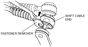
Shift cable
|
|
5
|
Clutch release cylinder
|
|
6
|
Transaxle mounting bolt (upper side)
|
|
7
|
Tie-rod end ball joint
|
|
8
|
Stabilizer control link
|
|
9
|
Lower arm ball joint
|
|
10
|
Drive shaft
|
|
11
|
Joint shaft
|
|
12
|
No.1 engine mount rubber
|
|
13
|
Battery tray bracket
|
|
14
|
No.4 engine mount rubber
|
|
15
|
No.4 engine mount bracket
|
|
16
|
Transaxle mounting bolt (lower side)
|
|
17
|
Manual transaxle
|
Shift Cable and Select Cable Removal Note
1. Remove the both shift cable end and select cable end using a fastener remover.
am3zzw00004950
|
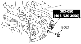
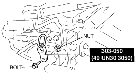
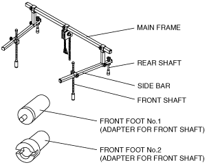
No.4 Engine Mount Removal Note
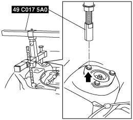
1. Using the bolts part number 99794 1025 or M10×1.25, length 25 mm {0.98 in} to install the SST to the position shown in the figure.
am3zzw00004951
|
am3zzw00004952
|
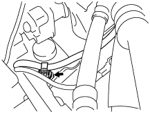
2. To install the front shaft (RH) of the SST (49 C017 5A0), remove the clip shown in the figure.
am3zzw00004953
|
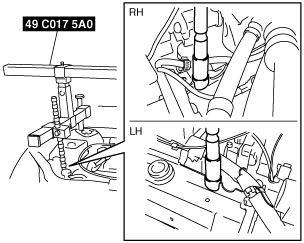
3. Install the SST using the following procedure.
am3zzw00004954
|
am3zzw00004955
|
am3zzw00004956
|
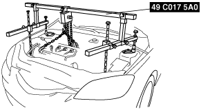
4. Support the engine using the SST.
am3zzw00004957
|
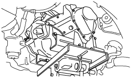
5. Remove the battery tray bracket, No.4 engine mount rubber and bracket.
Manual Transaxle Removal Note
1. Adjust the SST and lean the engine toward the transaxle.
am3zzw00004957
|
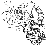
2. Support the transaxle on a jack.
am3zzw00004958
|
3. Remove the transaxle mounting bolts.
4. Remove the transaxle.
Manual Transaxle Installation Note
1. Set the transaxle on a jack and lift into place.
am3zzw00004959
|
2. Install the transaxle mounting bolts.
3. Adjust the SST (49 C017 5A0) so that the engine is located at the specified position.
No.1 Engine Mount and No.4 Engine Mount Bracket Installation Note
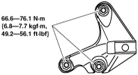
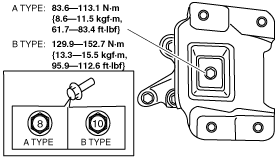
1. Install the No.4 engine mount bracket on the transaxle case and tighten nuts.
am3zzw00004948
|
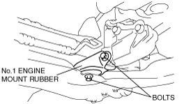
2. Install the No.1 engine mount rubber to the cross member and temporarily tighten bolts.
am3zzw00004960
|
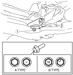
3. Place the No.4 engine mount rubber with the body stud bolts passing through the holes and tighten the bolt in the figure.
am3zzw00004605
|
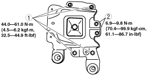
4. Place the battery tray bracket on the No.4 engine mount rubber with body stud bolts passing through the holes and tighten bolts and nuts in the order as shown in the figure.
am3zzw00004527
|
5. Remove the SSTs.
6. Install the clip as shown in the figure.
am3zzw00004953
|
7. Fully tighten the bolts.
am3zzw00004961
|