 |
am3zzw00013240
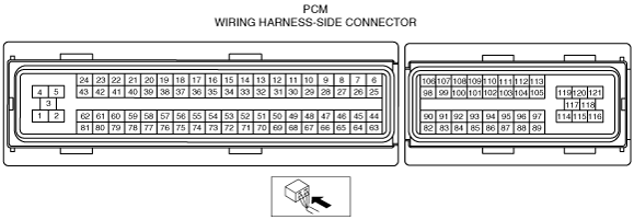
PCM INSPECTION [MZR-CD (RF Turbo)]
id0140f1802500
Without Using the SST
am3zzw00013240
|
|
Terminal |
Signal |
Connected to |
Test condition |
Voltage (V) |
Inspection item |
|
|---|---|---|---|---|---|---|
|
1
|
Ground
|
Body ground
|
Under any condition
|
Below 1.0
|
• Inspect related harness
|
|
|
2
|
Ground
|
Body ground
|
Under any condition
|
Below 1.0
|
• Inspect related harness
|
|
|
3
|
Ground
|
Body ground
|
Under any condition
|
Below 1.0
|
• Inspect related harness
|
|
|
4
|
Common
|
Fuel injector
(No.1, No.2, No.3, No.4)
|
Inspect using the wave Profile.
|
Below 1.0
|
• Inspect related harness
• Fuel injector (No.1, No.2, No.3, No.4)
|
|
|
5
|
—
|
—
|
—
|
—
|
—
|
|
|
6
|
VBC solenoid valve
|
VBC solenoid valve
|
Inspect using the wave Profile.
|
• Inspect related harness
• VBC solenoid valve
|
||
|
7
|
EGR valve (EGR-)
|
EGR valve
|
Idle
|
Below 1.0
|
• Inspect related harness
• EGR valve
|
|
|
8
|
EGR valve (EGR+)
|
EGR valve
|
Inspect using the wave Profile.
|
• Inspect related harness
• EGR valve
|
||
|
9
|
Generator field coil control
|
Generator
|
Inspect using the wave Profile.
|
• Inspect related harness
• Generator
|
||
|
10
|
Suction control valve
|
Suction control valve
|
Inspect using the wave Profile.
|
• Inspect related harness
• Suction control valve
|
||
|
11
|
—
|
—
|
—
|
—
|
—
|
|
|
12
|
Middle pressure
|
Refrigerant pressure switch (middle)
|
Refrigerant pressure switch (middle) ON
|
Below 1.0
|
• Inspect related harness
|
|
|
Refrigerant pressure switch (middle) OFF
|
B+
|
|||||
|
13
|
—
|
—
|
—
|
—
|
—
|
|
|
14
|
—
|
—
|
—
|
—
|
—
|
|
|
15
|
—
|
—
|
—
|
—
|
—
|
|
|
16
|
—
|
—
|
—
|
—
|
—
|
|
|
17
|
—
|
—
|
—
|
—
|
—
|
|
|
18
|
—
|
—
|
—
|
—
|
—
|
|
|
19
|
—
|
—
|
—
|
—
|
—
|
|
|
20
|
—
|
—
|
—
|
—
|
—
|
|
|
21
|
Fuel injector (#2)
|
Fuel injector No.2
|
Inspect using the wave Profile.
|
• Inspect related harness
• Fuel injector No.2
|
||
|
22
|
—
|
—
|
—
|
—
|
—
|
|
|
23
|
Fuel injector (#3)
|
Fuel injector No.3
|
Inspect using the wave Profile.
|
• Inspect related harness
• Fuel injector No.3
|
||
|
24
|
—
|
—
|
—
|
—
|
—
|
|
|
25
|
Fan control
|
Fan control module
|
Inspect using the wave Profile.
|
• Inspect related harness
• Fan control module
|
||
|
26
|
A/C
|
A/C relay
|
A/C operating
|
Below 1.0
|
• Inspect related harness
• A/C relay
|
|
|
A/C not operating
|
B+
|
|||||
|
27
|
—
|
—
|
—
|
—
|
—
|
|
|
28
|
—
|
—
|
—
|
—
|
—
|
|
|
29
|
Suction control valve
|
Suction control valve
|
Under any condition
|
Below 1.0
|
• Inspect related harness
• Suction control valve
|
|
|
30
|
Test
|
Check connector (Test connector)
|
—
|
—
|
—
|
|
|
31
|
—
|
—
|
—
|
—
|
—
|
|
|
32
|
High pressure
|
Refrigerant pressure switch (high)
|
Engine switch ON
|
Below 1.0
|
• Inspect related harness
|
|
|
33
|
Exhaust gas temp (Lower)
|
Exhaust gas temperature sensor (Lower)
|
Exhaust gas temperature 50 °C {122 °F}
|
Approx. 5
|
• Inspect related harness
• Exhaust gas temp sensor (Lower)
|
|
|
34
|
O2 sensor heater control
|
O2 sensor heater
|
Inspect using the wave Profile.
|
• Inspect related harness
• O2 sensor heater
|
||
|
35
|
Ground
|
Body ground
|
Under any condition
|
Below 1.0
|
• Inspect related harness
|
|
|
36
|
—
|
—
|
—
|
—
|
—
|
|
|
37
|
Glow
|
Glow plug relay
|
15 s from when engine switch is turned to ON position with ECT at 20 °C {68 °F} or less
|
B+
|
• Inspect related harness
• Glow plug relay
|
|
|
Idle
|
Below 1.0
|
|||||
|
38
|
—
|
—
|
—
|
—
|
—
|
|
|
39
|
Starter
|
Engine switch, Starter relay
|
Cranking
|
Below 1.0
|
• Inspect related harness
|
|
|
40
|
Fuel injection (#4)
|
Fuel injector No.4
|
Inspect using the wave Profile.
|
• Inspect related harness
• Fuel injector No.4
|
||
|
41
|
—
|
—
|
—
|
—
|
—
|
|
|
42
|
Fuel injection (#1)
|
Fuel injector No.1
|
Inspect using the wave Profile.
|
• Inspect related harness
• Fuel injector No.1
|
||
|
43
|
—
|
—
|
—
|
—
|
—
|
|
|
44
|
Constant voltage (Vref)
|
Fuel pressure sensor
|
Engine switch ON
|
Approx. 5
|
• Inspect related harness
• Fuel pressure sensor
|
|
|
45
|
Constant voltage (Vref)
|
EGR valve, Intake shutter valve, CKP sensor
|
Engine switch ON
|
Approx. 5
|
• Inspect related harness
• EGR valve
• Intake shutter valve
• CKP sensor
|
|
|
46
|
CKP (NE+)
|
CKP sensor
|
Inspect using the wave Profile.
|
• Inspect related harness
• CKP sensor
|
||
|
47
|
CMP (G+)
|
CMP sensor
|
Inspect using the wave Profile.
|
• Inspect related harness
• CMP sensor
|
||
|
48
|
Fuel pressure
|
Fuel pressure sensor
|
Engine switch ON
|
Approx. 1.0
|
• Inspect related harness
• Fuel pressure sensor
|
|
|
Engine speed is 3,000 rpm
|
Approx. 2.0
|
|||||
|
49
|
—
|
—
|
—
|
—
|
—
|
|
|
50
|
Fuel temp
|
Fuel temperature sensor
|
Engine switch ON
|
Fuel temperature
40 °C {104 °F}
|
Approx. 1.6
|
• Inspect related harness
• Fuel temperature sensor
|
|
Fuel temperature
45 °C {113 °F}
|
Approx. 1.3
|
|||||
|
51
|
ECT
|
ECT sensor
|
Engine switch ON
|
ECT 30 °C
{86 °F}
|
Approx. 2.61
|
• Inspect related harness
• ECT sensor
|
|
ECT 50 °C
{122 °F}
|
Approx. 1.72
|
|||||
|
ECT 60 °C
{140 °F}
|
Approx. 1.41
|
|||||
|
ECT 80 °C
{176 °F}
|
Approx. 0.88
|
|||||
|
52
|
MAP
|
Boost sensor
|
Engine switch ON
|
Approx. 1.0
|
• Inspect related harness
• Boost sensor
|
|
|
Idle
|
Approx. 0.6
|
|||||
|
53
|
EGR position
|
EGR valve
|
Engine switch ON
|
Below 1.0
|
• Inspect related harness
• EGR valve
|
|
|
EGR valve opening angle 36.5%
|
Approx. 2
|
|||||
|
54
|
MAF
|
MAF/IAT sensor
|
Engine switch ON
|
Approx. 0.8
|
• Inspect related harness
• Exhaust gas temp sensor (Lower)
|
|
|
Idle
|
Approx. 1.6
|
|||||
|
55
|
IAT
|
MAF/IAT sensor
|
Engine switch ON
|
IAT 30 °C
{86 °F}
|
Approx. 1.9
|
• Inspect related harness
• MAF/IAT sensor
|
|
IAT 40 °C
{104 °F}
|
Approx. 1.47
|
|||||
|
56
|
Exhaust gas temp (Upper)
|
Exhaust gas temperature sensor (Upper)
|
Exhaust gas temperature 50 °C {122 °F}
|
Approx. 5
|
• Inspect related harness
• Exhaust gas temperature sensor (Upper)
|
|
|
57
|
Exhaust gas temp (Middle)
|
Exhaust gas temperature sensor (Middle)
|
Exhaust gas temperature 50 °C {122 °F}
|
Approx. 5
|
• Inspect related harness
• Exhaust gas temperature sensor (Middle)
|
|
|
58
|
Press correction temp
|
Exhaust gas pressure correction temperature sensor
|
Engine switch ON
|
Near temperature of sensor 20 °C {68 °F}
|
Approx. 2.3
|
• Inspect related harness
• Exhaust gas pressure correction temperature sensor
|
|
Near temperature of sensor 80 °C {176 °F}
|
Approx. 0.5
|
|||||
|
59
|
Constant voltage (Vref)
|
Boost sensor
|
Engine switch ON
|
Approx. 5
|
• Inspect related harness
• Boost sensor
|
|
|
60
|
Constant voltage (Vref)
|
Exhaust gas pressure sensor
|
Engine switch ON
|
Approx. 5
|
• Inspect related harness
• Exhaust gas pressure sensor
|
|
|
61
|
Ground
|
Exhaust gas temperature sensor (Upper, Middle)
|
Under any condition
|
Below 1.0
|
• Inspect related harness
• Exhaust gas temp sensor (upper, middle)
|
|
|
62
|
Ground
|
Exhaust gas pressure sensor
|
Under any condition
|
Below 1.0
|
• Inspect related harness
• Exhaust gas pressure sensor
|
|
|
63
|
Constant voltage (Vref)
|
APP sensor
|
Engine switch ON
|
Approx. 5
|
• Inspect related harness
• APP sensor
|
|
|
64
|
Constant voltage (Vref)
|
CMP sensor
|
Engine switch ON
|
Approx. 5
|
• Inspect related harness
• CMP sensor
|
|
|
65
|
CKP (NE-)
|
CKP sensor
|
Idle
|
Below 1.0
|
• Inspect related harness
• CKP sensor
|
|
|
66
|
CMP (G-)
|
CMP sensor
|
Idle
|
Below 1.0
|
• Inspect related harness
• CMP sensor
|
|
|
67
|
—
|
—
|
—
|
—
|
—
|
|
|
68
|
Ground
|
Exhaust gas pressure correction temperature sensor
|
Under any condition
|
Below 1.0
|
• Inspect related harness
• Exhaust gas pressure correction temperature sensor
|
|
|
69
|
Ground
|
Fuel pressure sensor
|
Under any condition
|
Below 1.0
|
• Inspect related harness
• Fuel pressure sensor
|
|
|
70
|
Ground
|
ECT sensor, Fuel temperature sensor, Intake shutter valve EGR valve
|
Under any condition
|
Below 1.0
|
• Inspect related harness
• ECT sensor
• Fuel temperature sensor
• Intake shutter valve
• EGR valve
|
|
|
71
|
Ground
|
Boost sensor
|
Under any condition
|
Below 1.0
|
• Inspect related harness
• Boost sensor
|
|
|
72
|
Ground
|
Exhaust gas temperature sensor (lower)
|
Under any condition
|
Below 1.0
|
• Inspect related harness
• Exhaust gas temperature sensor (lower)
|
|
|
73
|
Ground
|
MAF/IAT sensor
|
Under any condition
|
Below 1.0
|
• Inspect related harness
• MAF/IAT sensor
|
|
|
74
|
Ground
|
IAT sensor No.2
|
Under any condition
|
Below 1.0
|
• Inspect related harness
• IAT sensor No.2
|
|
|
75
|
Glow
|
Glow plug
|
15s from 20 °C {68 °F} or less in water temperature and engine switch ON
|
B+
|
• Inspect related harness
• Glow plug
• Glow plug relay
|
|
|
Engine running after warm up
|
Below 1.0
|
|||||
|
76
|
—
|
—
|
—
|
—
|
—
|
|
|
77
|
Generator output voltage
|
Generator
|
Inspect using the wave Profile.
|
• Inspect related harness
|
||
|
78
|
Ground
|
MAF/IAT sensor
|
Under any condition
|
Below 1.0
|
• Inspect related harness
• MAF/IAT sensor
|
|
|
79
|
IAT
|
IAT sensor No.2
|
Engine switch ON
|
IAT 30 °C
{86 °F}
|
Approx. 1.9
|
• Inspect related harness
• IAT sensor No.2
|
|
IAT 40 °C
{104 °F}
|
Approx. 1.47
|
|||||
|
80
|
—
|
—
|
—
|
—
|
—
|
|
|
81
|
Exhaust gas pressure
|
Exhaust gas pressure sensor
|
Engine switch ON
|
Approx. 1.0
|
• Inspect related harness
• Exhaust gas pressure sensor
|
|
|
Idle
|
Approx. 1.2
|
|||||
|
82
|
Constant voltage (Vref)
|
APP sensor
|
Engine switch ON
|
Approx. 5
|
• Inspect related harness
• APP sensor
|
|
|
83
|
APP
|
APP sensor
|
Accelerator pedal released
|
Approx. 1.04
|
• Inspect related harness
• APP sensor
|
|
|
Accelerator pedal depressed
|
Approx. 3.35
|
|||||
|
84
|
Ground
|
APP sensor
|
Under any condition
|
Below 1.0
|
• Inspect related harness
• APP sensor
|
|
|
85
|
HO2S
|
HO2S
|
Idle
|
Approx. 2.1
|
• Inspect related harness
• HO2S
|
|
|
86
|
Intake shutter valve position
|
Intake shutter valve
|
Idle
|
Clutch pedal released
|
Approx. 0.75
|
• Inspect related harness
• Intake shutter valve
|
|
Clutch pedal depressed
|
Approx. 3.9
|
|||||
|
87
|
CAN (L)
|
Instrument cluster, ABS HU/CM, DSC HU/CM
|
Because this terminal is for CAN, good/no good judgment by terminal voltage is not possible
|
• Inspect related harness
|
||
|
88
|
—
|
—
|
—
|
—
|
—
|
|
|
89
|
—
|
—
|
—
|
—
|
—
|
|
|
90
|
—
|
—
|
—
|
—
|
—
|
|
|
91
|
APP
|
APP sensor
|
Accelerator pedal released
|
Approx. 1.58
|
• Inspect related harness
• APP sensor
|
|
|
Accelerator pedal depressed
|
Approx. 3.89
|
|||||
|
92
|
Ground
|
APP sensor
|
Under any condition
|
Below 1.0
|
• Inspect related harness
• APP sensor
|
|
|
93
|
HO2S
|
HO2S
|
Idle: Approx. 0 mA
|
—
|
• Inspect related harness
• HO2S
|
|
|
94
|
—
|
—
|
—
|
—
|
—
|
|
|
95
|
CAN (H)
|
Instrument cluster, ABS HU/CM, DSC HU/CM
|
Because this terminal is for CAN, good/no good judgment by terminal voltage is not possible
|
• Inspect related harness
|
||
|
96
|
—
|
—
|
—
|
—
|
—
|
|
|
97
|
—
|
—
|
—
|
—
|
—
|
|
|
98
|
—
|
—
|
—
|
—
|
—
|
|
|
99
|
Starter
|
Engine switch, Starter relay
|
Engine switch ON (START) position
|
B+
|
• Inspect related harness
• Engine switch
• Main fuse
|
|
|
Except for engine switch ON (START) position
|
Below 1.0
|
|||||
|
100
|
Brake
|
Brake switch No.1
|
Brake pedal depressed
|
B+
|
• Inspect related harness
• Brake switch
|
|
|
Brake pedal released
|
Below 1.0
|
|||||
|
101
|
—
|
—
|
—
|
—
|
—
|
|
|
102
|
Auto cruise
|
Auto cruise switch
|
Cruise main SW ON
|
Approx. 0
|
• Inspect related harness
• Auto cruise switch
|
|
|
Cancel SW ON
|
Approx. 1.8
|
|||||
|
Set/ Cost SW ON
|
Approx. 3.8
|
|||||
|
Res/ Acc SW ON
|
Approx. 4.6
|
|||||
|
Other
|
Approx. 5.0
|
|||||
|
103
|
Ground
|
Auto cruise switch
|
Under any condition
|
Below 1.0
|
• Inspect related harness
• Auto cruise switch
|
|
|
104
|
—
|
—
|
—
|
—
|
—
|
|
|
105
|
Main relay control
|
Main relay
|
Engine switch ON
|
Below 1.0
|
• Inspect related harness
• Main relay
|
|
|
Engine switch OFF
|
B+
|
|||||
|
106
|
—
|
—
|
—
|
—
|
—
|
|
|
107
|
IG 1
|
Engine switch
|
Engine switch is ON and Start position
|
B+
|
• Inspect related harness
|
|
|
Engine switch is other position
|
Below 1.0
|
|||||
|
108
|
—
|
—
|
—
|
—
|
—
|
|
|
109
|
Clutch
|
Clutch switch
|
Clutch pedal depressed
|
Below 1.0
|
• Inspect related harness
• Clutch switch
|
|
|
Clutch pedal released
|
B+
|
|||||
|
110
|
Neutral
|
Neutral switch
|
Neutral
|
Below 1.0
|
• Inspect related harness
• Neutral switch
|
|
|
Other
|
B+
|
|||||
|
111
|
PSP
|
Power steering switch
|
Steering wheel at straight ahead position
|
B+
|
• Inspect related harness
• PSP switch
|
|
|
While turning steering wheel
|
Below 1.0
|
|||||
|
112
|
—
|
—
|
—
|
—
|
—
|
|
|
113
|
—
|
—
|
—
|
—
|
—
|
|
|
114
|
Ground
|
Body ground
|
Under any condition
|
Below 1.0
|
• Inspect related harness
|
|
|
115
|
—
|
—
|
—
|
—
|
—
|
|
|
116
|
Intake shutter valve (ISV+)
|
Intake shutter valve
|
Idle
|
0 ÛB+
|
• Inspect related harness
• Intake shutter valve
|
|
|
117
|
Ground
|
Body ground
|
Under any condition
|
Below 1.0
|
• Inspect related harness
|
|
|
118
|
Intake shutter valve (ISV-)
|
Intake shutter valve
|
Idle
|
0 ÛB+
|
• Inspect related harness
• Intake shutter valve
|
|
|
119
|
B+
|
Main relay
|
Main relay ON
|
B+
|
• Inspect related harness
• Main relay
|
|
|
Main relay OFF
|
Below 1.0
|
|||||
|
120
|
B+
|
Main relay
|
Main relay ON
|
B+
|
• Inspect related harness
• Main relay
|
|
|
Main relay OFF
|
Below 1.0
|
|||||
|
121
|
Power supply
|
Power supply
|
Under any condition
|
B+
|
• Inspect related harness
|
|
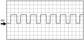
Inspection Using An Oscilloscope (Reference)
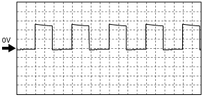
Common signal
am3zzw00013241
|
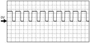
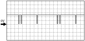
VBC solenoid valve signal
am3zzw00013242
|
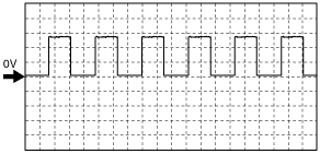
EGR valve (ISV+) signal
am3zzw00013243
|
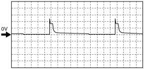
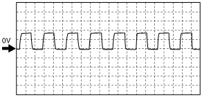
Generator field coil control signal
am3zzw00013244
|
Suction control valve signal
am3zzw00013245
|
Fuel injection signal
am3zzw00013246
|
Fan control signal
am3zzw00013247
|
HO2S heater control signal
am3zzw00013248
|
CKP (NE+) signal
am3zzw00013249
|
CMP (G+) signal
am3zzw00013250
|
Generator signal
am3zzw00013251
|
Using M-MDS
1. Connect the M-MDS to the DLC-2. (See ON-BOARD DIAGNOSTIC TEST [MZR-CD (RF Turbo)].)
2. Measure the PID value.
3. Turn the engine switch to ON.
PID Monitor Table
|
Monitor item (Definition) |
Unit/Condition |
Condition/Specification (Reference) |
Inspection item |
PCM terminal |
||||||
|---|---|---|---|---|---|---|---|---|---|---|
|
AC_REQ
(A/C switch)
|
On/Off
|
Refrigerant pressure switch is off: Off
Others: On
|
A/C switch
|
12, 32
|
||||||
|
ACCS
(Air conditioning compressor cycling switch)
|
On/Off
|
A/C switch ON and fan switch ON: On
Others: Off
|
Inspect following PIDs:
APP, ECT
|
26
|
||||||
|
ALTF
(Generator field coil control duty value)
|
%
|
Engine switch ON: 0%
Idle: 0—100%
|
Inspect following PIDs:
IAT, ECT, RPM, ALTT V
|
9
|
||||||
|
ALTT V
(Generator output voltage)
|
V
|
Engine switch ON: 0 V
Idle: Approx. 10 V
|
Generator
|
77
|
||||||
|
APP
(Accelerator pedal position)
|
%
|
Accelerator pedal released: 0%
Accelerator pedal depressed: 100%
|
Inspect following PIDs:
APP1, APP2
|
83, 91
|
||||||
|
APP_LRN
(Accelerator pedal position)
|
V
|
Displays accelerator pedal position fully-closed learning value.
|
Inspect following PIDs:
APP1, APP2
|
83, 91
|
||||||
|
APP1
(Accelerator pedal position)
|
%
|
Accelerator pedal released: 0%
Accelerator pedal depressed: 100%
|
APP sensor
|
83
|
||||||
|
V
|
Accelerator pedal released:
Approx. 1.04 V
Accelerator pedal depressed:
Approx. 3.35 V
|
|||||||||
|
APP2
(Accelerator pedal position)
|
%
|
Accelerator pedal released: 0%
Accelerator pedal depressed: 100%
|
APP sensor
|
91
|
||||||
|
V
|
Accelerator pedal released:
Approx. 1.58 V
Accelerator pedal depressed:
Approx. 3.89 V
|
|||||||||
|
ARPMDES
(Target engine speed)
|
RPM
|
No load: 725—825 rpm
E/L operating: 725—825 rpm
P/S operating: 725—825 rpm
A/C ON: 725—825 rpm
|
Inspect following PIDs:
AC_REQ, IAT, IAT2, ECT, BOOST_DSD, FRP, FRP_A, RPM, VSS
|
—
|
||||||
|
B+
(Battery positive voltage)
|
V
|
Indicate the battery positive voltage.
|
Battery
Main relay
|
119, 120, 121
|
||||||
|
BARO
(Barometric pressure)
|
Pa
|
Indicate Barometric pressure.
|
BARO sensor
|
—
|
||||||
|
V
|
BARO 101.3 kPa: Approx. 3.6V
|
|||||||||
|
BOO
(Brake switch)
|
On/Off
|
Brake pedal released: Off
Brake pedal depressed: On
|
Brake switch
|
100
|
||||||
|
BOOST_DSD (Desired boost pressure)
|
Pa
|
Desired boost pressure is displayed.
|
Perform applicable DTC troubleshooting.
|
—
|
||||||
|
CATT11_DSD
(Desired catalyst temperature)
|
°C
|
Indicate the catalyst temperature.
(Before exhaust gas passes through catalyst converter.)
|
—
|
56
|
||||||
|
CATT12_DSD
(Desired catalyst temperature)
|
°C
|
Indicate the catalyst temperature.
(After exhaust gas passes through diesel particulate filter.)
|
—
|
57
|
||||||
|
CATT21_DSD
(Desired catalyst temperature)
|
°C
|
Indicate the catalyst temperature.
(Before exhaust gas passes through diesel particulate filter.)
|
—
|
33
|
||||||
|
CHRGLP
(Generator warning light)
|
On/Off
|
Engine switch ON: On
Idle: Off
|
Perform applicable DTC troubleshooting.
|
—
|
||||||
|
DEC_CMP
(Fuel correction for deceleration)
|
—
|
Fuel correction for deceleration is displayed.
|
—
|
—
|
||||||
|
DSC_ACT
(DSC control enable/disable)
|
Enabled/Disabled
|
Engine switch ON: Disable
|
—
|
—
|
||||||
|
Idle: Enabled
|
||||||||||
|
DTCCNT
(DTC count)
|
—
|
Number of DTCs stored in the PCM is displayed.
|
Perform applicable DTC troubleshooting.
|
—
|
||||||
|
ECT
(Engine coolant temperature)
|
°C
|
Engine coolant temperature is displayed.
|
Inspect ECT sensor.
|
51
|
||||||
|
V
|
ECT 30 °C {86 °F}: Approx. 2.61 V
ECT 50 °C {122 °F}: Approx. 1.72 V
ECT 60 °C {140 °F}: Approx. 1.41 V
ECT 80 °C {176 °F}: Approx. 0.88 V
|
|||||||||
|
EGR_LRN
(EGR valve)
|
mm
|
Displays EGR valve fully-closed learning value.
|
EGR valve
|
53
|
||||||
|
EGRP
(EGR valve)
|
V
|
EGR valve opening angle 36.5%: Approx. 2 V
|
EGR valve
|
|||||||
|
mm
|
EGR valve opening angle 40%:
Approx. 4 mm
|
|||||||||
|
%
|
Displays EGR valve opening angle.
|
|||||||||
|
EQ_RAT11
(Oxygen sensor)
|
—
|
Idle: 1.99
|
Inspect following PIDs:
IAT, IAT2, ECT, O2S11
|
85, 93
|
||||||
|
ETC_ACT
(Electronic throttle control actual)
|
°
|
Engine switch ON: Approx. 91°
Idle: Approx. 3.2°
|
Perform applicable DTC troubleshooting.
|
86
|
||||||
|
ETC_DSD
(Electronic throttle control desired)
|
%
|
Indicate the desired throttle position by angle.
|
Inspect following PIDs:
APP1, APP2, ETC_ACT
|
83, 91, 86
|
||||||
|
°
|
Engine switch ON: Approx. 80°
Idle: Approx. 3.37°
|
|||||||||
|
EXHPRESS_LRN
(Exhaust gas pressure sensor)
|
Pa
|
Displays exhaust gas pressure learning value.
|
Exhaust pressure sensor
|
81
|
||||||
|
EXHPRESS2
(Exhaust gas pressure sensor)
|
Pa
|
Indicates the exhaust gas pressure sensor (differential).
|
Exhaust pressure sensor
|
81
|
||||||
|
EXHTEMP1
(Exhaust gas temperature sensor)
|
°C
|
Indicate the exhaust gas temperature.
|
Exhaust gas temperature sensor (upper)
|
56
|
||||||
|
EXHTEMP2
(Exhaust gas temperature sensor)
|
°C
|
Indicate the exhaust gas temperature.
|
Exhaust gas temperature sensor (middle)
|
57
|
||||||
|
EXHTEMP3
(Exhaust gas temperature sensor)
|
°C
|
Indicate the exhaust gas temperature.
|
Exhaust gas temperature sensor (lower)
|
33
|
||||||
|
FAN_DUTY
(Fan control module)
|
%
|
Idle
|
A/C switch off: 0%
A/C switch ON:
Approx. 65%
|
Fun control module
|
25
|
|||||
|
Fl_LRN_01
(Fuel injector No.1)
|
ms
|
Displays injector correction value.
|
Fuel injector No.1
|
42
|
||||||
|
Fl_LRN_02
(Fuel injector No.2)
|
ms
|
Displays injector correction value.
|
Fuel injector No.2
|
21
|
||||||
|
Fl_LRN_03
(Fuel injector No.3)
|
ms
|
Displays injector correction value.
|
Fuel injector No.3
|
23
|
||||||
|
Fl_LRN_04
(Fuel injector No.4)
|
ms
|
Displays injector correction value.
|
Fuel injector No.4
|
40
|
||||||
|
Fl_LRN_11
(Fuel injector No.1)
|
ms
|
Displays injector correction value.
|
Fuel injector No.1
|
42
|
||||||
|
Fl_LRN_12
(Fuel injector No.2)
|
ms
|
Displays injector correction value.
|
Fuel injector No.2
|
21
|
||||||
|
Fl_LRN_13
(Fuel injector No.3)
|
ms
|
Displays injector correction value.
|
Fuel injector No.3
|
23
|
||||||
|
Fl_LRN_14
(Fuel injector No.4)
|
ms
|
Displays injector correction value.
|
Fuel injector No.4
|
40
|
||||||
|
Fl_LRN_21
(Fuel injector No.1)
|
ms
|
Displays injector correction value.
|
Fuel injector No.1
|
42
|
||||||
|
Fl_LRN_22
(Fuel injector No.2)
|
ms
|
Displays injector correction value.
|
Fuel injector No.2
|
21
|
||||||
|
Fl_LRN_23
(Fuel injector No.3)
|
ms
|
Displays injector correction value.
|
Fuel injector No.3
|
23
|
||||||
|
Fl_LRN_24
(Fuel injector No.4)
|
ms
|
Displays injector correction value.
|
Fuel injector No.4
|
40
|
||||||
|
Fl_LRN_31
(Fuel injector No.1)
|
ms
|
Displays injector correction value.
|
Fuel injector No.1
|
42
|
||||||
|
Fl_LRN_32
(Fuel injector No.2)
|
ms
|
Displays injector correction value.
|
Fuel injector No.2
|
21
|
||||||
|
Fl_LRN_33
(Fuel injector No.3)
|
ms
|
Displays injector correction value.
|
Fuel injector No.3
|
23
|
||||||
|
Fl_LRN_34
(Fuel injector No.4)
|
ms
|
Displays injector correction value.
|
Fuel injector No.4
|
40
|
||||||
|
FIA_DSD
(Fuel injector)
|
—
|
Indicate the desired injector correction.
|
Fuel injector
|
—
|
||||||
|
FIP_FL
(Supply pump flow control)
|
A
|
Idle: Approx. 1.7 A
|
Inspect following PIDs:
AC_REQ, IAT, IAT2, ECT, BOOST_DSD, FRP, FRP_A, RPM, VSS
|
—
|
||||||
|
FIP_FL_DSD
(Supply pump flow desired)
|
—
|
Engine switch ON: Approx. 0 mm3/stroke
Idle: Approx. 55 mm3/stroke
|
Inspect following PIDs:
AC_REQ, IAT, IAT2, ECT, BOOST_DSD, FRP, FRP_A, RPM, VSS
|
—
|
||||||
|
FIP_LRN
(Supply pump learning amount)
|
A
|
Indicate the supply pump learning amount.
|
Inspect following PIDs:
AC_REQ, IAT, IAT2, ECT, BOOST_DSD, FRP, FRP_A, RPM, VSS
|
—
|
||||||
|
FIP_SCV
(Supply pump suction control valve)
|
A
|
Engine switch ON: Approx. 0 mA
Idle: 1.67—1.73 A
|
Inspect following PIDs:
AC_REQ, IAT, IAT2, ECT, BOOST_DSD, FRP, FRP_A, RPM, VSS
|
10, 29
|
||||||
|
FLT
(Fuel temperature)
|
°C
|
Fuel temperature is displayed.
|
Fuel temperature sensor
|
50
|
||||||
|
FP
(Fuel pump relay)
|
%
|
Idle: Approx. 45%
|
Inspect following PIDs: RPM
|
—
|
||||||
|
FRP
(Fuel pressure sensor)
|
V
|
Engine switch ON: Approx. 1 V
|
Fuel pressure sensor
|
48
|
||||||
|
Idle: Approx. 1.54 V
3,000 rpm: Approx. 2.0 V
|
||||||||||
|
Pa
|
Engine switch ON: 0 kPa {0 psi, 0 Bar}
|
|||||||||
|
Idle: Approx. 34 MPa {4,931 psi, 340 Bar}
2,000 rpm: Approx. 43 MPa {6,237 psi, 430 Bar}
|
||||||||||
|
FRP_A
(FRP after fuel injection)
|
Pa
|
Engine switch ON: 0 kPa {0 psi, 0 Bar}
|
||||||||
|
Idle: Approx. 34 MPa {4,931 psi, 340 Bar}
2,000 rpm: Aprrox.43 MPa {6,237 psi, 430 Bar}
|
||||||||||
|
GENVDSD
(Generator voltage desired)
|
V
|
Indicate the generator voltage desired.
|
Perform applicable DTC troubleshooting.
|
—
|
||||||
|
GLWPG_V
(Glow plugs)
|
V
|
Approx. 0 V
|
Inspect following PIDs:
ECT, BOOST_DSD, VSS
|
37
|
||||||
|
Cranking: Approx. 10 V
Idle: Approx. 0 V
|
||||||||||
|
GP_LMP
(Glow indicator light)
|
On/Off
|
Glow indicator light Off: Off
Glow indicator light ON: On
|
||||||||
|
GPC
(Glow plug control)
|
On/Off
|
Engine switch ON: Off
|
||||||||
|
Cranking: On
Idle: Off
|
||||||||||
|
HTR11
(O2S heater control)
|
%
|
Engine switch ON: 0%
|
Inspect following PIDs:
IAT, IAT2, MAF, TP1, ECT, RPM
|
34
|
||||||
|
ohms
|
Engine switch ON: Approx. 500 ohms
|
|||||||||
|
HTR11_Off
(O2S heater control)
|
V
|
Engine switch ON: Approx. 0.02 V
|
Inspect following PIDs:
IAT, IAT2, MAF, TP1, ECT, RPM
|
|||||||
|
HTR11_On
(O2S heater control)
|
V
|
Engine switch ON: 0V
|
Inspect following PIDs:
IAT, IAT2, MAF, TP1, ECT, RPM
|
|||||||
|
IAT
(Intake air temperature)
|
V
|
30°C {86 °F}: Approx. 1.9 V
40°C {104 °F}: Approx. 1.47 V
|
IAT sensor
|
55
|
||||||
|
°C
|
Intake air temperature is display
|
|||||||||
|
IAT2
(Intake air temperature)
|
V
|
30°C {86 °F}: Approx. 1.9 V
40°C {104 °F}: Approx. 1.47 V
|
IAT sensor No.2
|
79
|
||||||
|
°C
|
Intake air temperature is display
|
|||||||||
|
ICP
(Injector control pressure)
|
Pa
|
35 MPa {5,076 psi, 350 Bar}
|
Inspect following PIDs:
AC_REQ, IAT, IAT2, ECT, BOOST_DSD, FRP, FRP_A, RPM, VSS
|
—
|
||||||
|
Idle: Approx.35 MPa {5,076 psi, 350 Bar}
2,000 rpm: Approx.45 MPa {6,526.7 psi, 450 Bar}
|
||||||||||
|
ICP_DSD
(Injector control pressure desired)
|
Pa
|
Engine switch ON: 0 Pa
Idle: Approx. 35 Kpa
|
Inspect following PIDs:
AC_REQ, IAT, IAT2, ECT, BOOST_DSD, FRP, FRP_A, RPM, VSS
|
—
|
||||||
|
ISV_LRN_C
(Intake shatter valve)
|
%
|
Idle: Approx. 2%
|
Intake shutter valve
|
86
|
||||||
|
ISV_LRN_O
(Intake shatter valve)
|
%
|
Idle: Approx. 80%
|
Intake shutter valve
|
|||||||
|
LOAD
(Engine load)
|
%
|
Engine switch ON: 0%
Idle: Approx. 8.62%
|
MAF sensor
|
—
|
||||||
|
MAF
(Mass airflow amount)
|
g/s
|
Engine switch ON: 0 g/s
Idle: Approx. 13 g/s
2,000 rpm: Approx. 21 g/s
|
MAF sensor
|
54
|
||||||
|
V
|
Engine switch ON: Approx. 0.8 V
Idle: Approx. 1.6 V
2,000 rpm: Approx. 2.4 V
|
|||||||||
|
MAF_C
(MAF per cylinder)
|
g
|
Engine switch ON: Approx. 1.05 mg
Idle: Approx. 215 mg
2,000 rpm: Approx. 300 mg
|
MAF sensor
|
54
|
||||||
|
MAF_C_DSD
(MAF per cylinder desired)
|
g
|
Engine switch ON: Approx. 1.01 mg
Idle: Approx. 260 mg
2,000 rpm: Approx. 300 mg
|
MAF sensor
|
—
|
||||||
|
MAP
(Manifold absolute pressure)
|
Pa
|
Manifold absolute pressure is displayed.
|
MAP sensor
|
52
|
||||||
|
V
|
Engine switch ON: Approx. 1.0 V
Idle: Approx. 0.6 V
|
|||||||||
|
MIL
(Malfunction indicator lamp)
|
On/Off
|
Engine switch ON: On
|
Perform applicable DTC troubleshooting.
|
—
|
||||||
|
Idle: Off
|
||||||||||
|
MIL_DIS
(Travelled distance since the MIL illuminated)
|
Km
|
Indicate the travelled distance since the MIL illuminated.
|
—
|
|||||||
|
O2
(HO2S)
|
%
|
Engine switch ON: Approx. 0%
|
HO2S
|
85, 93
|
||||||
|
O2S11
(HO2S)
|
A
|
Engine switch ON: Approx. 0 A
|
HO2S
|
|||||||
|
O2S11_CAL
(HO2S)
|
—
|
Displays HO2S calibration value.
|
HO2S
|
|||||||
|
OIL_DIL
(Engine oil dilution amount)
|
g
|
Indicate the engine oil dilution amount.
|
—
|
—
|
||||||
|
OILCHG_DIS
(Distance since last oil change)
|
Km
|
Indicate the distance since last oil change.
|
—
|
—
|
||||||
|
OILCHG_DIS2
(Distance since last oil change 2 (Correction value))
|
Km
|
Indicate the distance since last oil change 2 (Correction value).
|
—
|
—
|
||||||
|
PM_ACC
(PM accumulation amount)
|
—
|
Displays PM accumulation amount.
|
—
|
—
|
||||||
|
PM_ACC_DSD
(PM accumulation amount desired)
|
—
|
Displays PM accumulation amount.
|
—
|
—
|
||||||
|
PM_GEN
(PM generation amount)
|
—
|
Displays PM generation amount.
|
—
|
—
|
||||||
|
REG_AUTO
(Diesel particulate filter)
|
On/Off
|
Diesel particulate filter auto regeneration operated: ON
|
—
|
—
|
||||||
|
REG_MAN
(Diesel particulate filter)
|
On/Off
|
Diesel particulate filter manual regeneration operated: ON
|
—
|
—
|
||||||
|
RPM
(Engine speed)
|
RPM
|
Engine switch ON: 0 RPM
|
CKP sensor
|
46, 65
|
||||||
|
Idle
|
No load: 700—850 RPM
E/L operating: 700—850 RPM
P/S operating: 700—850 RPM
A/C ON: 700—850 RPM
|
|||||||||
|
SC_CANCEL
(Cruise cancel switch)
|
Active/Inactive
|
Cruise cancel switch released: Inactive
Cruise cancel switch depressed: Active
|
Cruise control switch
|
102
|
||||||
|
SC_COAST
(Cruise coast switch)
|
Active/Inactive
|
Cruise coast switch released: Inactive
Cruise coast switch depressed: Active
|
Cruise control switch
|
|||||||
|
SC_MAIN
(Cruise main switch)
|
Active/Inactive
|
Cruise control switch OFF: Inactive
Cruise control switch ON: Active
|
Cruise control switch
|
|||||||
|
SC_MODE
(Cruise control switch)
|
Off/Standby/Active/Tap-up/Set/Tap-down/Coast
|
Displays cruise operation mode.
|
Cruise control switch
|
|||||||
|
SC_ON
(Cruise control switch)
|
On/Off
|
Cruise main indicator light ON: On
Cruise main indicator light Off: Off
|
Cruise control switch
|
|||||||
|
SC_RES
(Cruise resume switch)
|
Active/Inactive
|
Cruise resume switch released: Inactive
Cruise resume switch depressed: Active
|
Cruise control switch
|
|||||||
|
SC_SET
(Cruise control switch)
|
On/Off
|
Cruise set switch ON: Active
Cruise set switch Off: Inactive
|
Cruise control switch
|
|||||||
|
SC_SET/ACC
(Cruise control switch)
|
Active/Inactive
|
Cruise res accel switch ON: Active
Cruise res accel switch Off: Inactive
|
Cruise control switch
|
|||||||
|
SCCS
(Cruise control switch)
|
V
|
Engine switch ON: 5 V
|
Cruise control switch
|
|||||||
|
TC_CMP
(Fuel correction for traction control)
|
—
|
Fuel correction for traction control is display.
|
Inspect following PIDs:
AC_REQ, APP1, APP2, IAT2, ECT, BOOST_DSD, FRP, FRP_A, RPM, VSS
|
—
|
||||||
|
TIRESIZE
(Tire revolution per mile)
|
rev/mile
|
Indicate the tire revolution per a mile.
|
—
|
—
|
||||||
|
TP1
(Intake shutter valve)
|
%
|
Intake shutter valve opening angle display.
|
Intake shutter valve position sensor
|
86
|
||||||
|
V
|
Clutch pedal released: Approx. 0.75 V
Clutch pedal depressed: Approx. 3.9 V
|
|||||||||
|
VBCV
(VBC solenoid valve control)
|
%
|
Engine switch ON: 5.32%
Idle: Approx. 46%
2,000 rpm: Approx. 45%
|
Inspect following PIDs: MAF, ECT, RPM
Inspect VBC solenoid valve.
|
6
|
||||||
|
VSS
(Vehicle speed)
|
KPH
|
Vehicle speed is displayed.
|
Perform applicable DTC troubleshooting.
|
—
|
||||||