 |
am3zzw00004221
EXHAUST GAS PRESSURE CORRECTION TEMPERATURE SENSOR INSPECTION [MZR-CD (RF Turbo)]
id0140f1446200
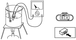
Resistance Inspection
1. Remove the exhaust gas pressure correction temperature sensor. (See EXHAUST GAS PRESSURE SENSOR/EXHAUST GAS PRESSURE CORRECTION TEMPERATURE SENSOR REMOVAL/INSTALLATION [MZR-CD (RF Turbo)].)
2. Place the exhaust gas pressure correction temperature sensor in water with a thermometer, and heat the water gradually.
3. Measure the resistance between the exhaust gas pressure correction temperature sensor terminals using an ohmmeter.
Specification
|
Water temperature (°C {°F}) |
Resistance (kilohm) |
|---|---|
|
20 {68}
|
2.21—2.69
|
|
80 {176}
|
0.29—0.35
|
am3zzw00004221
|
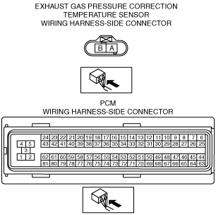
Circuit Open/Short Inspection
1. Disconnect the PCM connector. (See PCM REMOVAL/INSTALLATION [MZR-CD (RF Turbo)].)
2. Inspect for open/short circuit in the following wiring harnesses.
am3zzw00004222
|
Open circuit
Short circuit