EXHAUST GAS PRESSURE SENSOR INSPECTION [MZR-CD (RF Turbo)]
id0140f1446000
-
Caution
-
• Because the output characteristics of the exhaust gas pressure sensor are adjusted while it is installed to the bracket, replace the exhaust gas pressure sensor and the bracket as a single unit.
-
Note
-
• Perform the following test only when directed.
Voltage Inspection
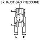
1. While the connector is connected, remove the hoses attached to exhaust gas pressure sensor ports A and B.
2. Turn the engine switch to ON.
3. Verify that the voltage at PCM terminal 81 is within the specification.
-
• If not as specified, perform the “Circuit Open/Short Inspection”.
-
4. Verify that the voltage variance at PCM terminal 81 is within the specification when a pressure of 0—100 Kpa is applied to exhaust gas pressure sensor port A.
-
• If not as specified, perform the “Circuit Open/Short Inspection”.
-
-
Voltage variance
-
1.0—4.5 V
Circuit Open/Short Inspection
1. Disconnect the PCM connector. (See PCM REMOVAL/INSTALLATION [MZR-CD (RF Turbo)].)
2. Inspect for open/short circuit in the following wiring harnesses.
-
• If there is open/short circuit, repair or replace wiring harness.
Open circuit
-
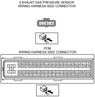
• Exhaust gas pressure sensor terminal A and PCM terminal 62
• Exhaust gas pressure sensor terminal B and PCM terminal 81
• Exhaust gas pressure sensor terminal C and PCM terminal 60
Short circuit
-
• Exhaust gas pressure sensor terminal A and power supply
• Exhaust gas pressure sensor terminal A and body ground
• Exhaust gas pressure sensor terminal B and power supply
• Exhaust gas pressure sensor terminal B and body ground
• Exhaust gas pressure sensor terminal C and power supply
• Exhaust gas pressure sensor terminal C and body ground