 |
am3zzw00001035
PCM INSPECTION [MZ-CD 1.6 (Y6)]
id0140b2802500
Not Using the M-MDS
PCM terminal voltage table (Reference)
|
Terminal |
Signal name |
Connected to |
Measurement condition |
Voltage (V) |
Inspection item(s) |
|
|---|---|---|---|---|---|---|
|
101
|
Fuel injector No.1 control signal ”high”
|
Fuel injector No.1
|
• Fuel injector No.1
• Related wiring harness
|
|||
|
102
|
Fuel injector No.4 control signal ”high”
|
Fuel injector No.4
|
• Fuel injector No.4
• Related wiring harness
|
|||
|
103
|
Fuel temperature sensor ground
|
Fuel temperature sensor
|
Under any condition
|
1.0 or less
|
• Fuel temperature sensor
• Related wiring harness
|
|
|
104
|
Variable boost control signal
|
Variable boost control solenoid valve
|
• Variable boost control solenoid valve
• Related wiring harness
|
|||
|
105
|
Sensor ground
|
Air bypass valve position sensor*2, intake throttle valve position sensor
|
Under any condition
|
1.0 or less
|
• Related wiring harness
|
|
|
106
|
—
|
—
|
—
|
—
|
—
|
|
|
107
|
Generator command
|
Generator
|
• Generator
• Related wiring harness
|
|||
|
108
|
Starter control signal
|
Starter relay
|
Under any condition
|
1.0 or less
|
• Starter relay
• Related wiring harness
|
|
|
109
|
Fuel injector No.3 control signal ”high”
|
Fuel injector No.3
|
• Fuel injector No.3
• Related wiring harness
|
|||
|
110
|
Fuel injector No.2 control signal ”high”
|
Fuel injector No.2
|
• Fuel injector No.2
• Related wiring harness
|
|||
|
111
|
—
|
—
|
—
|
—
|
—
|
|
|
112
|
A/C control signal
|
A/C relay
|
Under any condition
|
1.0 or less
|
• A/C relay
• Related wiring harness
|
|
|
113
|
—
|
—
|
—
|
—
|
—
|
|
|
114*2
|
—
|
—
|
—
|
—
|
—
|
|
|
114*1
|
Catalyst exhaust gas temperature sensor ground
|
Catalyst exhaust gas temperature sensor
|
Under any condition
|
1.0 or less
|
• Catalyst exhaust gas temperature sensor
• Related wiring harness
|
|
|
115
|
—
|
—
|
—
|
—
|
—
|
|
|
116
|
—
|
—
|
—
|
—
|
—
|
|
|
117
|
Fuel injector No.4 control signal ”low”
|
Fuel injector No.4
|
• Fuel injector No.4
• Related wiring harness
|
|||
|
118
|
Fuel injector No.1 control signal ”low”
|
Fuel injector No.1
|
• Fuel injector No.1
• Related wiring harness
|
|||
|
119*2
|
—
|
—
|
—
|
—
|
—
|
|
|
119*1
|
Diesel particulate filter differential pressure sensor ground
|
Diesel particulate filter differential pressure sensor
|
Under any condition
|
1.0 or less
|
• Diesel particulate filter differential pressure sensor
• Related wiring harness
|
|
|
120
|
—
|
—
|
—
|
—
|
—
|
|
|
121
|
EGR valve position sensor ground
|
EGR valve position sensor
|
Under any condition
|
1.0 or less
|
• EGR valve position sensor
• Related wiring harness
|
|
|
122
|
—
|
—
|
—
|
—
|
—
|
|
|
123
|
—
|
—
|
—
|
—
|
—
|
|
|
124
|
MAF sensor signal
|
MAF sensor
|
KOEO
|
Approx. 8.2
|
• MAF sensor
• Related wiring harness
|
|
|
KOER
|
Idle
|
Approx. 10
|
||||
|
2,000 rpm
|
Approx. 11.5
|
|||||
|
125
|
Fuel injector No.3 control signal ”low”
|
Fuel injector No.3
|
• Fuel injector No.3
• Related wiring harness
|
|||
|
126
|
Fuel injector No.2 control signal ”low”
|
Fuel injector No.2
|
• Fuel injector No.2
• Related wiring harness
|
|||
|
127
|
—
|
—
|
—
|
—
|
—
|
|
|
128
|
—
|
—
|
—
|
—
|
—
|
|
|
129
|
EGR valve position sensor signal
|
EGR valve position sensor
|
KOEO
|
Approx. 0.86
|
• EGR valve
• Related wiring harness
|
|
|
KOER
|
Idle
|
Approx. 2.8
|
||||
|
2,000 rpm
|
||||||
|
130
|
—
|
—
|
—
|
—
|
—
|
|
|
131
|
—
|
—
|
—
|
—
|
—
|
|
|
132
|
Glow time feed back input signal state
|
Glow plug relay
|
KOEO
|
Approx. 11
|
• Glow plug relay
• Related wiring harness
|
|
|
KOER
|
Idle
|
1.0 or less
|
||||
|
2,000 rpm
|
||||||
|
201
|
EGR valve position sensor supply
|
EGR valve position sensor
|
KOEO/KOER
|
Approx. 5
|
• EGR valve
• Related wiring harness
|
|
|
202
|
Fuel pressure sensor supply
|
Fuel pressure sensor
|
KOEO/KOER
|
Approx. 5
|
• Fuel pressure sensor
• Related wiring harness
|
|
|
203
|
Fuel pressure sensor ground
|
Fuel pressure sensor
|
Under any condition
|
1.0 or less
|
• Fuel pressure sensor
• Related wiring harness
|
|
|
204
|
MAP sensor ground
|
MAP sensor
|
Under any condition
|
1.0 or less
|
• MAP sensor
• Related wiring harness
|
|
|
205
|
MAP sensor supply
|
MAP sensor
|
KOEO/KOER
|
Approx. 5
|
• MAP sensor
• Related wiring harness
|
|
|
206
|
Constant voltage (Vref)
|
CMP sensor, intake throttle valve position sensor, air bypass valve position sensor*2
|
KOEO/KOER
|
Approx. 5
|
• Related wiring harness
|
|
|
207*2
|
—
|
—
|
—
|
—
|
—
|
|
|
207*1
|
Diesel particulate filter differential pressure sensor supply
|
Diesel particulate filter differential pressure sensor
|
KOEO/KOER
|
Approx. 5
|
• Diesel particulate filter differential pressure sensor
• Related wiring harness
|
|
|
208
|
—
|
—
|
—
|
—
|
—
|
|
|
209
|
—
|
—
|
—
|
—
|
—
|
|
|
210
|
Glow plug control signal
|
Glow plug relay
|
Engine switch off
|
B+
|
• Glow plug relay
• Related wiring harness
|
|
|
KOEO
|
Approx. 9.7
|
|||||
|
KOER
|
Idle
|
Approx. 10.7
|
||||
|
2,000 rpm
|
||||||
|
211
|
IAT sensor No.2 ground
|
IAT sensor No.2
|
Under any condition
|
1.0 or less
|
• IAT sensor No.2
• Related wiring harness
|
|
|
212
|
Fuel metering valve control signal
|
Fuel metering valve
|
• Fuel metering valve
• Related wiring harness
|
|||
|
213
|
Generator state signal
|
Generator
|
KOEO
|
1.0 or less
|
• Generator
• Related wiring harness
|
|
|
KOER
|
Idle
|
Approx. 2.6
|
||||
|
2,000 rpm
|
Approx. 1.2
|
|||||
|
214
|
—
|
—
|
—
|
—
|
—
|
|
|
215
|
—
|
—
|
—
|
—
|
—
|
|
|
216
|
—
|
—
|
—
|
—
|
—
|
|
|
217
|
—
|
—
|
—
|
—
|
—
|
|
|
218
|
CKP sensor supply
|
CKP sensor
|
KOEO/KOER
|
Approx. 5
|
• CKP sensor
• Related wiring harness
|
|
|
219
|
Fuel pressure sensor signal
|
Fuel pressure sensor
|
KOEO
|
Approx. 0.5
|
• Fuel pressure sensor
• Related wiring harness
|
|
|
KOER
|
Idle
|
Approx. 1.0
|
||||
|
2,000 rpm
|
Approx. 1.6
|
|||||
|
220*2
|
—
|
—
|
—
|
—
|
—
|
|
|
220*1
|
Catalyst exhaust gas temperature sensor signal
|
Catalyst exhaust gas temperature sensor
|
Exhaust gas temperature:100°C {212 °F}
|
Approx. 4.83
|
• Catalyst exhaust gas temperature sensor
• Related wiring harness
|
|
|
Exhaust gas temperature:150°C {302 °F}
|
Approx. 4.51
|
|||||
|
Exhaust gas temperature:200°C {392 °F}
|
Approx. 3.98
|
|||||
|
Exhaust gas temperature:250°C {482 °F}
|
Approx. 3.22
|
|||||
|
Exhaust gas temperature:300°C {572°F}
|
Approx. 2.43
|
|||||
|
Exhaust gas temperature:350°C {662 °F}
|
Approx. 1.74
|
|||||
|
Exhaust gas temperature:400°C {752 °F}
|
Approx. 1.24
|
|||||
|
Exhaust gas temperature:450°C {842 °F}
|
Approx. 0.89
|
|||||
|
Exhaust gas temperature:500°C {932 °F}
|
Approx. 0.64
|
|||||
|
Exhaust gas temperature:550°C {1,022 °F}
|
Approx. 0.47
|
|||||
|
Exhaust gas temperature:600°C {1,112 °F}
|
Approx. 0.36
|
|||||
|
Exhaust gas temperature:650°C {1,202 °F}
|
Approx. 0.27
|
|||||
|
Exhaust gas temperature:700°C {1,292 °F}
|
Approx. 0.21
|
|||||
|
221
|
—
|
—
|
—
|
—
|
—
|
|
|
222
|
Intake throttle valve position sensor signal
|
Intake throttle valve position sensor
|
—
|
—
|
• Intake throttle valve
• Related wiring harness
|
|
|
223
|
—
|
—
|
—
|
—
|
—
|
|
|
224
|
—
|
—
|
—
|
—
|
—
|
|
|
225
|
—
|
—
|
—
|
—
|
—
|
|
|
226
|
—
|
—
|
—
|
—
|
—
|
|
|
227
|
EGR valve servo motor control signal (plus)
|
EGR valve servo motor
|
• EGR valve
• Related wiring harness
|
|||
|
228
|
EGR valve servo motor control signal (minus)
|
EGR valve servo motor
|
Under any condition
|
1.0 or less
|
• EGR valve
• Related wiring harness
|
|
|
229
|
MAF/IAT sensor ground
|
MAF/IAT sensor
|
Under any condition
|
1.0 or less
|
• MAF/IAT sensor
• Related wiring harness
|
|
|
230
|
ECT sensor signal
|
ECT sensor
|
Engine coolant temperature:30°C {86°F}
|
Approx. 2.6
|
• ECT sensor
• Related wiring harness
|
|
|
Engine coolant temperature:70°C {158°F}
|
Approx. 1.1
|
|||||
|
231
|
IAT sensor signal
|
IAT sensor
|
Intake air temperature:29°C {84.2°F}
|
Approx. 2.2
|
• IAT sensor
• Related wiring harness
|
|
|
Intake air temperature:33°C {91.4°F}
|
Approx. 1.8
|
|||||
|
232
|
Fuel temperature sensor signal
|
Fuel temperature sensor
|
Fuel temperature:43°C {109.4°F}
|
Approx. 1.49
|
• Fuel temperature sensor
• Related wiring harness
|
|
|
Fuel temperature:47°C {116.6°F}
|
Approx. 1.37
|
|||||
|
233*2
|
—
|
—
|
—
|
—
|
—
|
|
|
233*1
|
Air bypass valve position sensor signal
|
Air bypass valve position sensor
|
—
|
—
|
• Air bypass valve
• Related wiring harness
|
|
|
234
|
MAP sensor signal
|
MAP sensor
|
KOEO
|
Approx. 2.4
|
• MAP sensor
• Related wiring harness
|
|
|
KOER
|
MAP: 103 kPa {773 mmHg, 30 inHg}
|
Approx. 2.43
|
||||
|
MAP: 150 kPa {1125 mmHg, 44 inHg}
|
Approx. 3.3
|
|||||
|
235
|
—
|
—
|
—
|
—
|
—
|
|
|
236
|
Power supply
|
PCM control relay
|
KOEO/KOER
|
B+
|
• PCM control relay
• Related wiring harness
|
|
|
237
|
CMP sensor ground
|
CMP sensor
|
Under any condition
|
1.0 or less
|
• CMP sensor
• Related wiring harness
|
|
|
238
|
CKP sensor signal
|
CKP sensor
|
• CKP sensor
• Related wiring harness
|
|||
|
239
|
CKP sensor ground
|
CKP sensor
|
Under any condition
|
1.0 or less
|
• CKP sensor
• Related wiring harness
|
|
|
240
|
CMP sensor signal
|
CMP sensor
|
• CMP sensor
• Related wiring harness
|
|||
|
241
|
Power supply
|
PCM control relay
|
Engine switch is off
|
B+
|
• PCM control relay
• Related wiring harness
|
|
|
KOEO
|
1.0 or less
|
|||||
|
KOER
|
Idle
|
|||||
|
2,000 rpm
|
||||||
|
242
|
IAT sensor No.2 signal
|
IAT sensor No.2
|
—
|
—
|
• IAT sensor No.2
• Related wiring harness
|
|
|
243
|
—
|
—
|
—
|
—
|
—
|
|
|
244
|
ECT sensor ground
|
ECT sensor
|
Under any condition
|
1.0 or less
|
• ECT sensor
• Related wiring harness
|
|
|
245
|
—
|
—
|
—
|
—
|
—
|
|
|
246
|
Diesel particulate filter differential pressure sensor signal
|
Diesel particulate filter differential pressure sensor
|
Diesel particulate filter differential pressure:0 kPa {0 kgf/cm2, 0 psi}
|
Approx. 0.50
|
• Diesel particulate filter differential pressure sensor
• Related wiring harness
|
|
|
Diesel particulate filter differential pressure:5 kPa {0.051 kgf/cm2, 0.73 psi}
|
Approx. 0.77
|
|||||
|
Diesel particulate filter differential pressure:10 kPa {0.102 kgf/cm2, 1.45 psi}
|
Approx. 1.03
|
|||||
|
Diesel particulate filter differential pressure:15 kPa {0.153 kgf/cm2, 2.18 psi}
|
Approx. 1.30
|
|||||
|
Diesel particulate filter differential pressure:20 kPa {0.204 kgf/cm2, 2.90 psi}
|
Approx. 1.57
|
|||||
|
Diesel particulate filter differential pressure:25 kPa {0.255 kgf/cm2, 3.63 psi}
|
Approx. 1.83
|
|||||
|
Diesel particulate filter differential pressure:30 kPa {0.306 kgf/cm2, 4.35 psi}
|
Approx. 2.10
|
|||||
|
Diesel particulate filter differential pressure:35 kPa {0.357 kgf/cm2, 5.08 psi}
|
Approx. 2.37
|
|||||
|
Diesel particulate filter differential pressure:40 kPa {0.408 kgf/cm2, 5.80 psi}
|
Approx. 2.63
|
|||||
|
Diesel particulate filter differential pressure:45 kPa {0.459 kgf/cm2, 6.53 psi}
|
Approx. 2.90
|
|||||
|
Diesel particulate filter differential pressure:50 kPa {0.510 kgf/cm2, 7.25 psi}
|
Approx. 3.17
|
|||||
|
Diesel particulate filter differential pressure:55 kPa {0.561 kgf/cm2, 7.98 psi}
|
Approx. 3.43
|
|||||
|
Diesel particulate filter differential pressure:60 kPa {0.612 kgf/cm2, 8.70 psi}
|
Approx. 3.70
|
|||||
|
Diesel particulate filter differential pressure:65 kPa {0.663 kgf/cm2, 9.43 psi}
|
Approx. 3.97
|
|||||
|
Diesel particulate filter differential pressure:70 kPa {0.714 kgf/cm2, 10.2 psi}
|
Approx. 4.23
|
|||||
|
Diesel particulate filter differential pressure:75 kPa {0.765 kgf/cm2, 10.9 psi}
|
Approx. 4.50
|
|||||
|
247
|
Intake throttle valve actuator control signal
|
Intke throttle valve actuator
|
—
|
—
|
• Intake throttle valve
• Related wiring harness
|
|
|
248*2
|
—
|
—
|
—
|
—
|
—
|
|
|
248*1
|
Air bypass valve actuator control signal
|
Air bypass valve actuator
|
—
|
—
|
• Air bypass valve
• Related wiring harness
|
|
|
301
|
Controller area network (high)
|
Controller area network (high)
|
Because this terminal is for CAN, determination by terminal voltage is not possible.
|
• Related wiring harness
|
||
|
302
|
K-line
|
DLC-2
|
Because this terminal is for K-line, determination by terminal voltage is not possible.
|
• Related wiring harness
|
||
|
303
|
Fan state signal
|
A/C switch
|
Under any condition
|
1.0 or less
|
• A/C switch
• Related wiring harness
|
|
|
304
|
—
|
—
|
—
|
—
|
—
|
|
|
305
|
—
|
—
|
—
|
—
|
—
|
|
|
306
|
—
|
—
|
—
|
—
|
—
|
|
|
307
|
Ground
|
Body ground
|
Under any condition
|
1.0 or less
|
• Related wiring harness
|
|
|
308
|
Ground
|
Body ground
|
Under any condition
|
1.0 or less
|
• Related wiring harness
|
|
|
309
|
Controller area network (low)
|
Controller area network (low)
|
Because this terminal is for CAN, determination by terminal voltage is not possible.
|
• Related wiring harness
|
||
|
310
|
APP state signal
|
APP sensor
|
APP is fully opened
|
1.0 or less
|
• APP sensor
• Related wiring harness
|
|
|
APP is fully closed
|
Approx. 7.2
|
|||||
|
311
|
IG1 signal
|
engine switch
|
KOEO/KOER
|
B+
|
• engine switch
• Related wiring harness
|
|
|
312
|
—
|
—
|
—
|
—
|
—
|
|
|
313
|
Oil pressure signal
|
Oil pressure switch
|
KOEO
|
1.0 or less
|
• Oil pressure switch
• Related wiring harness
|
|
|
KOER
|
B+
|
|||||
|
314
|
—
|
—
|
—
|
—
|
—
|
|
|
315
|
A/C compressor pressure signal
|
Refrigerant pressure sensor
|
Under any condition
|
1.0 or less
|
• Refrigerant pressure sensor
• Related wiring harness
|
|
|
316
|
—
|
—
|
—
|
—
|
—
|
|
|
317
|
Brake state signal
|
Brake switch
|
KOEO/KOER
|
Brake pedal depressed
|
B+
|
• Brake switch
• Related wiring harness
|
|
Brake pedal released
|
1.0 or less
|
|||||
|
318
|
Fan control unit
|
Fan control unit
|
KOEO/KOER
|
The A/C is operating
|
Approx. 5
|
• Fan control unit
• Related wiring harness
|
|
The A/C is not operating
|
B+
|
|||||
|
319
|
—
|
—
|
—
|
—
|
—
|
|
|
320
|
—
|
—
|
—
|
—
|
—
|
|
|
321
|
—
|
—
|
—
|
—
|
—
|
|
|
322
|
—
|
—
|
—
|
—
|
—
|
|
|
323
|
—
|
—
|
—
|
—
|
—
|
|
|
324
|
—
|
—
|
—
|
—
|
—
|
|
|
326
|
—
|
—
|
—
|
—
|
—
|
|
|
327
|
—
|
—
|
—
|
—
|
—
|
|
|
328
|
—
|
—
|
—
|
—
|
—
|
|
|
329
|
—
|
—
|
—
|
—
|
—
|
|
|
330
|
—
|
—
|
—
|
—
|
—
|
|
|
331
|
Power supply
|
PCM control relay
|
KOEO/KOER
|
B+
|
• PCM control relay
• Related wiring harness
|
|
|
332
|
Ground
|
Body ground
|
Under any condition
|
1.0 or less
|
• Related wiring harness
|
|
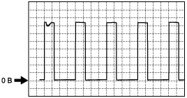
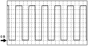
Inspection Using An Oscilloscope (Reference)
Fuel inject control signal (high)
am3zzw00001035
|
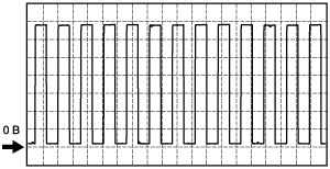
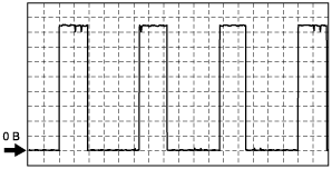
Variable boost control signal
am3zzw00001036
|
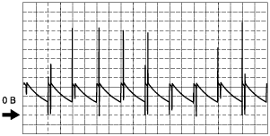
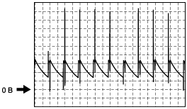
Generator command
am3zzw00001037
|
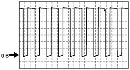
Fuel inject control signal (low)
am3zzw00001038
|
Fuel metering valve control signal
am3zzw00001039
|
EGR valve actuator control signal
am3zzw00001040
|
CKP sensor signal
am3zzw00001041
|
CMP sensor signal
am3zzw00001042
|
Using the M-MDS (reference)
PID monitor table
|
Item (Definition) |
Unit/ Condition |
Condition/Specification (Reference) |
Inspection item(s) |
PCM terminal |
|||
|---|---|---|---|---|---|---|---|
|
ABS_MSG
(The CAN communication with the ABS HU/CU)
|
Present/
Not Present
|
• The CAN communication with the ABS HU/CU is normal: Present
• The CAN communication with the ABS HU/CU malfunction: Not Present
|
• PCM
• ABS HUCU
• CAN
|
—
|
|||
|
ACCS
(A/C compressor cycling switch)
|
On/Off
|
• A/C is operating: On
• A/C is not operating: Off
|
• The following PIDs
|
112
|
|||
|
AC_LOWSW
(A/C compressor cycling switch)
|
On/Off
|
• A/C compressor cycling switch is 290 kPa {2.95 kgf/cm2, 42.0 psi} or more: On
• A/C compressor cycling switch is 145—158 kPa {14.8—1.61 kgf/cm2, 21.0—23.0 psi} or less: Off
|
• A/C compressor cycling switch
|
303
|
|||
|
ALTF
(Generator field current control duty signal)
|
%
|
• KOEO: Approx. 0—3 %
• Idling, E/L is operating: Duty value increases.
|
• The following PIDs
• Generator
|
107
|
|||
|
APP
(APP sensor)
|
%
|
• Accelerator pedal is released: 0 %
• Accelerator pedal is depressed: Approx. 99.6 %
|
• APP sensor
|
310
|
|||
|
APP
(APP sensor)
|
CT/PT/WOT
|
• Accelerator pedal is released: CT
• Accelerator pedal is depressed but has not been floored: PT
• Accelerator pedal is depressed: WOT
|
• APP sensor
|
310
|
|||
|
ARPMDES
(Target idle speed)
|
RPM
|
• Indicates the target idle speed
|
—
|
—
|
|||
|
AXLE
(Axle ratio)
|
No unit
|
• Indicates the final gear ratio
|
• PCM configuration
|
—
|
|||
|
BARO
(Barometric pressure)
|
Pa
|
Bar
|
psi
|
• Indicates the atmospheric pressure
|
• PCM
|
—
|
|
|
BOO
(Brake switch)
|
On/Off
|
• Brake pedal is depressed: On
• Brake pedal is released: Off
|
• Brake switch
|
317
|
|||
|
CABVDC
(Air bypass valve duty cycle)
|
%
|
• KOEO: 0 %
|
• Air bypass valve
|
248
|
|||
|
CABVP
(Air bypass valve position sensor)
|
%
|
• KOEO: 0 %
• Idling: 0 % (Note: It operates at the time of a diesel particulate filter regeneration.)
|
• Air bypass valve position sensor
|
233
|
|||
|
COLP
(Refrigerant pressure switch (medium pressure switch))
|
On/Off
|
• Refrigerant pressure switch (medium pressure switch) is 1.57—1.77 MPa {16.0—18.0 kgf/cm2, 227—257 psi} or more: On
• Refrigerant pressure switch (medium pressure switch) is 1.38 MPa {14.1 kgf/cm2, 200 psi} or less: Off
|
• Refrigerant pressure switch (medium-pressure switch)
|
315
|
|||
|
DPF_DIF
(Diesel particulate filter differential pressure sensor)
|
Pa
|
Bar
|
psi
|
• KOEO: 0 kPa {0 kgf/cm2, 0 psi}
• Idling: 0—1 kPa {0—0.010 kgf/cm2, 0—0.145 psi}
|
• Diesel particulate filter differential pressure sensor
|
246
|
|
|
DTCCNT
(DTC count)
|
No unit
|
• Number of DTCs stored
• When a DTC is not stored, “0” is indicated
|
• DTC
|
—
|
|||
|
ECT
(ECT sensor)
|
°C
|
°F
|
• Indicates the engine coolant temperature
|
• ECT sensor
|
230
|
||
|
EGR_TV
(Intake throttle valve position sensor)
|
%
|
• KOEO: 100 %
• Idling: 0—100 %
|
• Intake throttle valve position sensor
|
222
|
|||
|
EgrDc
(EGR valve)
|
%
|
• KOEO: 100 %
• Idling: Approx. 60—70 %
|
• EGR valve
|
228
|
|||
|
EGRVP
(EGR valve position sensor)
|
%
|
• KOEO: 0 %
• Idling: Approx. 30—40 %
|
• EGR valve position sensor
|
129
|
|||
|
EOT
(Engine oil temperature sensor)
|
°C
|
°F
|
• Indicates the engine oil temperature
|
• Engine oil temperature sensor
|
217
|
||
|
FAN_DUTY
(Fan control duty value)
|
%
|
• Engine coolant temperature is 80 °C or less: 0 %
• Engine coolant temperature is 85 °C: Approx. 20 %
• Engine coolant temperature is 90 °C: Approx. 40 %
|
• Fan control module
|
318
|
|||
|
FP
(Fuel pump)
|
%
|
• KOEO (Directly after turning the engine switch to the ON position or off): Approx. 35 %
• KOEO (After a certain period of time from turning the engine switch to the ON position): Approx. 15 %
• Idling: Approx. 35—40 %
|
• Fuel pump
|
212
|
|||
|
FRP
(Fuel pressure sensor)
|
Pa
|
Bar
|
psi
|
• KOEO: Approx. 430 kPa {4.4 kgf/cm2, 62.4 psi}
• Idling: Approx. 22—30 MPa {224.3—305.9 kgf/cm2, 3190.8—4351.1 psi}
|
• Fuel pressure sensor
|
219
|
|
|
FRT
(Fuel temperature sensor)
|
°C
|
°F
|
• Indicates the fuel temperature
|
• Fuel temperature sensor
|
232
|
||
|
GPC
(Glow plug relay)
|
On/Off
|
• Glow plug relay is operating: On
• Glow plug relay is not operating: Off
|
• Glow plug relay
|
132
|
|||
|
IAT
(IAT sensor)
|
°C
|
°F
|
• Indicates the intake air temperature
|
• IAT sensor
|
231
|
||
|
IC_MSG
(The CAN communication with the instrument cluster)
|
Present/
Not Present
|
• The CAN communication with the instrument cluster is normal: Present
• The CAN communication with the instrument cluster malfunction: Not Present
|
• CAN
• Instrument cluster
• PCM
|
—
|
|||
|
MAF
(MAF sensor)
|
g/s
|
• KOEO: 0 g/s
• KOER (Idling): Approx. 5—6 g/s
• KOER (2,000 rpm): Approx. 13—16 g/s
|
• MAF sensor
|
124
|
|||
|
MAP
(MAP sensor)
|
Pa
|
Bar
|
psi
|
• KOEO/KOER (Idling): Indicates the barometric pressure
• KOER (2,000 rpm): Approx. 100—110 kPa {1.02—1.12 kgf/cm2, 14.5—16.0 psi}
• KOER (3,000 rpm): Approx. 130—140 kPa {1.33—1.43 kgf/cm2, 18.9—20.3 psi}
|
• MAP sensor
|
234
|
|
|
MIL_DIS
(Travelled distance since MIL illuminated)
|
m
|
mile
|
• Indicates the travelled distance since the MIL illuminated
|
—
|
—
|
||
|
OPSW
(Oil pressure switch)
|
On/Off
|
• KOEO: On
• KOER: Off
|
• Oil pressure switch
|
313
|
|||
|
RPM
(Engine speed)
|
RPM
|
• Indicates the engine speed
|
• CKP sensor
|
238
|
|||
|
SELTESTDTC
(DTC)
|
NO unit
|
• Number of stored DTCs
|
—
|
—
|
|||
|
ST_EN_RLY
(Stater relay)
|
Enabled/Disabled
|
• Stater relay is operating: Enabled
• Stater relay is not operating: Disabled
|
• Stater relay
|
108
|
|||
|
TIRESIZE
(Tire revolution per mile)
|
rev/mile
|
• Indicates the tire revolution per a mile
|
—
|
—
|
|||
|
TORQUE
(Net engine torque)
|
Nm
|
• Indicates the net engine torque
|
—
|
—
|
|||
|
VBCV
(VBC solenoid valve)
|
%
|
• KOEO: Approx. 5 %
• KOER (Idling): Approx. 65—70 %
• KOER (2,000 rpm and No load): Approx. 55—60 %
|
• VBC solenoid valve
|
104
|
|||
|
VPWR
(Battery positive voltage)
|
V
|
• KOEO: B+
• Idling: B+
|
• Battery
• PCM control relay
|
307, 308, 332
|
|||
|
VSS
(Vehicle speed)
|
KPH
|
MPH
|
• Vehicle running: Indicates the vehicle speed
|
• VSS
|
214
|
||