|
1
|
VERIFY FREEZE FRAME DATA HAS BEEN RECORDED
• Has FREEZE FRAME DATA been recorded?
|
Yes
|
Go to the next step.
|
|
No
|
Record the FREEZE FRAME DATA on the repair order, then go to the next step.
|
|
2
|
VERIFY RELATED REPAIR INFORMATION AVAILABILITY
• Verify related service repair information availability.
• Is any related repair information available?
|
Yes
|
Perform repair or diagnosis according to the available repair information.
• If the vehicle is not repaired, go to the next step.
|
|
No
|
Go to the next step.
|
|
3
|
VERIFY CURRENT SIGNAL STATUS: IS CONCERN INTERMITTENT OR CONSTANT?
• Connect the M-MDS to the DLC-2.
• Clear the DTC from the PCM memory using the M-MDS.
• Start the engine.
• Is the same DTC present?
|
Yes
|
Go to the next step.
|
|
No
|
Intermittent concern exists.
Perform the “INTERMITTENT CONCERN TROUBLESHOOTING”.
|
|
4
|
FUEL INJECTOR CONNECTOR FOR POOR CONNECTION
• Turn the engine switch to the ON position.
• Inspect for poor connection (such as damaged/pulled- out terminals, corrosion).
• Is there any malfunction?
|
Yes
|
Repair or replace the terminal, then go to Step 14.
|
|
No
|
Go to the next step.
|
|
5
|
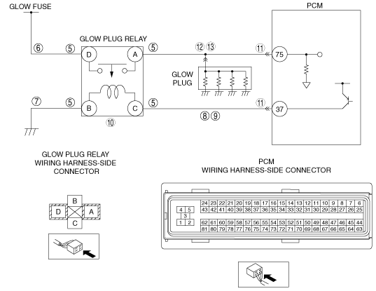
INSPECT GLOW PLUG RELAY CONNECTOR FOR POOR CONNECTION
• Turn the engine switch off.
• Disconnect the glow plug relay connector.
• Inspect for poor connection (such as damaged/pulled-out pins, corrosion).
• Is there any malfunction?
|
Yes
|
Repair or replace the terminal, then go to the next step.
|
|
No
|
Go to the next step.
|
|
6
|
INSPECT GLOW PLUG RELAY POWER SUPPLY FOR OPEN CIRCUIT
• Turn the engine switch off.
• Measure the voltage between glow plug relay terminal D and body ground.
• Is the voltage B+?
|
Yes
|
Go to the next step.
|
|
No
|
Repair or replace the wiring harness for an open circuit, go to Step 14.
|
|
7
|
INSPECT GLOW PLUG RELAY GROUND FOR OPEN CIRCUIT
• Turn the engine switch off.
• Remove the glow plug relay.
• Inspect for continuity between glow plug relay terminal B and ground.
• Is there continuity?
|
Yes
|
Go to the next step.
|
|
No
|
Repair or replace the wiring harness for an open circuit, go to Step 14.
|
|
8
|
INSPECT GLOW PLUG RELAY SIGNAL FOR OPEN CIRCUIT
• Turn the engine switch to the ON position (Engine off).
• Measure the voltage between glow plug relay terminal C.
• Is voltage less than 0.25 V?
|
Yes
|
Repair or replace the wiring harness for an open circuit, go to Step 14.
|
|
No
|
Go to the next step.
|
|
9
|
INSPECT GLOW PLUG RELAY SIGNAL CIRCUIT FOR SHORT TO GROUND
• Turn the engine switch off.
• Inspect for continuity between glow plug relay terminal C and body ground.
• Is there continuity?
|
Yes
|
Repair or replace the wiring harness for a short to ground, go to Step 14.
|
|
No
|
Go to the next step.
|
|
10
|
INSPECT GLOW PLUG RELAY
• Inspect the glow plug relay.
• Is there any malfunction?
|
Yes
|
Go to the next step.
|
|
No
|
Replace the glow plug relay, go to Step 14.
|
|
11
|
INSPECT POOR CONNECTION OF PCM CONNECTOR
• Turn the engine switch off.
• Inspect for poor connection (such as damaged/pulled-out terminals, corrosion).
• Is there any malfunction?
|
Yes
|
Repair or replace the suspected terminal, go to Step 14.
|
|
No
|
Go to the next step.
|
|
12
|
INSPECT GLOW PLUG RELAY SIGNAL CIRCUIT FOR SHORT TO GROUND
• Turn the engine switch off.
• Remove the glow plug connector.
• Inspect for continuity between glow plug relay terminal A and body ground.
• Is there continuity?
|
Yes
|
Repair or replace the wiring harness for a short to ground, then go to Step 14.
|
|
No
|
Go to the next step
|
|
13
|
INSPECT GLOW PLUG RELAY SIGNAL CIRCUIT FOR OPEN CIRCUIT
• Turn the engine switch off.
• Inspect for continuity between glow plug relay terminal A and PCM terminal 75.
• Is there continuity?
|
Yes
|
Go to the next step
|
|
No
|
Repair or replace the wiring harness for an open circuit, then go to the next step.
|
|
14
|
VERIFY TROUBLESHOOTING OF DTC P1391 COMPLETED
• Make sure to reconnect all disconnected connectors.
• Clear the DTC from the PCM memory using the M-MDS.
• Start the engine.
• Is the same DTC present?
|
Yes
|
Replace the PCM, go to the next step.
|
|
No
|
Go to the next step.
|
|
15
|
VERIFY AFTER REPAIR PROCEDURE
• Perform the Repair Verification Drive Mode.
• Are any DTCs present?
|
Yes
|
Go to the applicable DTC inspection.
|
|
No
|
Troubleshooting completed.
|