|
1
|
VERIFY FREEZE FRAME DATA HAS BEEN RECORDED
• Has FREEZE FRAME DATA been recorded?
|
Yes
|
Go to the next step.
|
|
No
|
Record the FREEZE FRAME DATA on the repair order, then go to the next step.
|
|
2
|
VERIFY RELATED REPAIR INFORMATION AVAILABILITY
• Verify related service repair information availability.
• Is any related repair information available?
|
Yes
|
Perform repair or diagnosis according to the available repair information.
• If the vehicle is not repaired, go to the next step.
|
|
No
|
Go to the next step.
|
|
3
|
IDENTIFY TRIGGER DTC FOR FREEZE FRAME DATA
• Is DTC P0140 on FREEZE FRAME DATA?
|
Yes
|
Go to the next step.
|
|
No
|
Go to troubleshooting procedures for DTC on FREEZE FRAME DATA.
|
|
4
|
VERIFY CURRENT INPUT SIGNAL STATUS
• Warm up engine.
• Access O2S11 PID using the M-MDS.
• Verify PID while racing engine in NEUTRAL.
• Is PID normal?
-
― Less than 1 mA when suddenly depressing accelerator pedal (rich condition)
― More than 1 mA just after releasing the accelerator pedal (lean condition)
|
Yes
|
Go to step 9.
|
|
No
|
Go to the next step.
|
|
5
|
INSPECT INSTALLATION OF A/F SENSOR
• Inspect if the A/F sensor is loosely installed.
• Is the sensor installed securely?
|
Yes
|
Go to the next step.
|
|
No
|
Install the sensor securely, then go to Step 11.
|
|
6
|
INSPECT GAS LEAKAGE FROM EXHAUST SYSTEM
• Visually inspect if there is any gas leakage between the exhaust manifold and A/F sensor.
• Is there gas leakage?
|
Yes
|
Repair or replace any malfunctioning exhaust part, then go to Step 11.
|
|
No
|
Go to the next step.
|
|
7
|
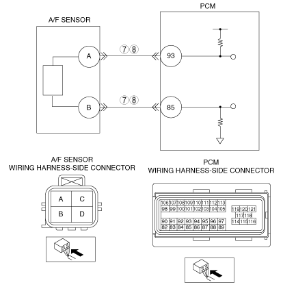
INSPECT A/F SENSOR CIRCUIT FOR OPEN CIRCUIT
• Inspect for continuity between the following terminals:
-
― A/F sensor terminal A (wiring harness-side) and PCM terminal 93 (wiring harness-side)
― A/F sensor terminal B (wiring harness-side) and PCM terminal 85 (wiring harness-side)
• Are there continuity?
|
Yes
|
Go to the next step.
|
|
No
|
Repair or replace the wiring harness for open circuit, then go to Step 11.
|
|
8
|
INSPECT A/F SENSOR CIRCUIT FOR SHORT TO GROUND
• Inspect for continuity between the following terminals:
-
― A/F sensor terminal A (wiring harness-side) and body ground
― A/F sensor terminal B (wiring harness-side) and body ground
• Are there continuity?
|
Yes
|
Repair or replace the wiring harness for short to ground, then go to Step 11.
|
|
No
|
Go to the next step.
|
|
9
|
INSPECT SEALING OF ENGINE COOLANT PASSAGE
• Perform the ENGINE COOLANT LEAKAGE INSPECTION.
• Is there any malfunction?
|
Yes
|
Repair or replace the malfunctioning part according to inspection results, then go to Step 11.
|
|
No
|
Go to the next step.
|
|
10
|
INSPECT ENGINE COMPRESSION
• Inspect the engine compression.
• Is it normal?
|
Yes
|
Go to the next step.
|
|
No
|
Perform engine overhaul for repairs, then go to the next step.
|
|
11
|
VERIFY TROUBLESHOOTING OF DTC P0140 COMPLETED
• Make sure to reconnect all disconnected connectors.
• Turn the engine switch to the ON position (Engine off).
• Clear the DTC from memory using the M-MDS.
• Start the engine.
• Perform the Repair Verification Drive Mode.
• Is the PENDING CODE for this DTC present?
|
Yes
|
Replace the PCM, then go to the next step.
|
|
No
|
Go to the next step.
|
|
12
|
VERIFY AFTER REPAIR PROCEDURE
• Perform the “After Repair Procedure”.
• Are any DTC present?
|
Yes
|
Go to the applicable DTC troubleshooting.
|
|
No
|
Troubleshooting completed.
|