|
1
|
VERIFY FREEZE FRAME DATA HAS BEEN RECORDED
• Has the FREEZE FRAME DATA been recorded?
|
Yes
|
Go to the next step.
|
|
No
|
Record the FREEZE FRAME DATA on the repair order, then go to the next step.
|
|
2
|
VERIFY REPAIR INFORMATION AVAILABILITY
• Verify related service repair information availability.
• Is any related repair information available?
|
Yes
|
Perform repair or diagnosis according to the available repair information.
If the vehicle is not repaired, go to the next step.
|
|
No
|
Go to the next step.
|
|
3
|
IDENTIFY TRIGGER DTC FOR FREEZE FRAME DATA
• Is P1922 on FREEZE FRAME DATA?
|
Yes
|
Go to the next step.
|
|
No
|
Go to troubleshooting procedures for DTC in FREEZE FRAME DATA.
|
|
4
|
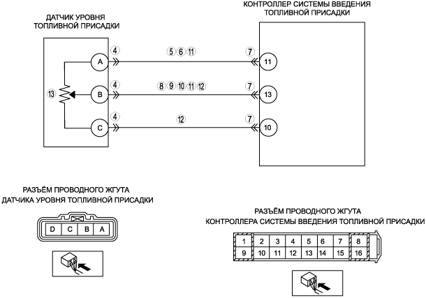
INSPECT FUEL ADDITIVE LEVEL SENSOR CONNECTOR FOR POOR CONNECTION
• Turn the engine switch off.
• Disconnect the fuel additive level sensor connector.
• Inspect poor connection (such as damaged, pulled-out terminals, corrosion, etc.).
• Is there any malfunction?
|
Yes
|
Repair or replace terminal, then go to Step 14.
|
|
No
|
Go to the next step.
|
|
5
|
INSPECT FUEL ADDITIVE LEVEL SENOR POWER SUPPLY CIRCUIT FOR OPEN
• Turn the engine switch to the ON position (Engine off).
• Measure the voltage between fuel additive level sensor terminal A (harness-side) and body ground.
• Is the voltage 4.5—5.5 V?
|
Yes
|
Go to the next step.
|
|
No
|
Repair for open circuit, then go to Step 14.
|
|
6
|
INSPECT FUEL ADDITIVE LEVEL SENSOR GROUND CIRCUIT FOR SHORT TO POWER
• Turn the engine switch to the ON position (Engine off).
• Measure the voltage between fuel additive level sensor terminal A (harness-side) and body ground.
• Is the voltage below 1.0 V?
|
Yes
|
Go to the next step.
|
|
No
|
Repair for short to power, then go to Step 14.
|
|
7
|
INSPECT FUEL ADDITIVE CONTROL MODULE CONNECTOR FOR POOR CONNECTION
• Turn the engine switch off.
• Disconnect fuel additive control module connector.
• Inspect poor connection (such as damaged, pulled-out terminals, corrosion, etc.).
• Is there any malfunction?
|
Yes
|
Repair or replace terminal, then go to Step 14.
|
|
No
|
Go to the next step.
|
|
8
|
INSPECT FUEL ADDITIVE LEVEL SENSOR SIGNAL CIRCUIT FOR SHORT TO POWER
• Turn the engine switch to the ON position (Engine off).
• Measure the voltage between fuel additive level sensor terminal B (harness-side) and body ground.
• Is the voltage below 1.0 V?
|
Yes
|
Go to the next step.
|
|
No
|
Repair or replace harness for short to power, then go to Step 14.
|
|
9
|
INSPECT FUEL ADDITIVE LEVEL SENSOR SIGNAL CIRCUIT FOR SHORT TO GROUND
• Turn the engine switch off.
• Inspect continuity between fuel additive level sensor terminal B (harness-side) and body ground.
• Is there any continuity?
|
Yes
|
Repair or replace harness for short to ground, then go to Step 14.
|
|
No
|
Go to the next step.
|
|
10
|
INSPECT FUEL ADDITIVE LEVEL SENSOR SIGNAL CIRCUIT FOR OPEN
• Inspect continuity connector between fuel additive level sensor terminal B (harness-side) and fuel additive control module terminal 13 (harness-side).
• Is there any continuity?
|
Yes
|
Repair or replace harness for open, then go to Step 14.
|
|
No
|
Go to the next step.
|
|
11
|
INSPECT FUEL LEVEL ADDITIVE LEVEL SENSOR SIGNAL CIRCUIT FOR SHORT TO POWER SUPPLY
• Inspect continuity between fuel additive level sensor terminal A and B (harness-side).
• Is there any continuity?
|
Yes
|
Repair or replace for short circuit, then go to Step 14.
|
|
No
|
Go to the next step.
|
|
12
|
INSPECT FUEL LEVEL ADDITIVE LEVEL SENSOR SIGNAL CIRCUIT FOR SHORT TO SENSOR GROUND
• Inspect continuity between fuel additive level sensor terminal B and C (harness-side).
• Is there any continuity?
|
Yes
|
Repair or replace for short circuit, then go to Step 14.
|
|
No
|
Go to the next step.
|
|
13
|
INSPECT FUEL ADDITIVE LEVEL SENSOR
• Inspect the fuel additive level sensor.
• Is the fuel additive level sensor normal?
|
Yes
|
Intermittent concern exits go to the next step.
|
|
No
|
Replace the fuel additive level sensor, then go to the next step.
|
|
14
|
VERIFY THAT DTC P1922 TROUBLESHOOTING IS COMPLETED
• Make sure to reconnect all disconnected connectors.
• Clear the DTC from the PCM memory using the M-MDS.
• Start the engine and warm-up to normal operating temperature.
• Run the vehicle under the FREEZE FRAME DATA stored condition.
• Retrieve the DTC using the M-MDS.
• Is the PENDING CODE same DTC present?
|
Yes
|
Replace fuel additive control module, then go to the next step.
|
|
No
|
Go to the next step.
|
|
15
|
VERIFY AFTER REPAIR PROCEDURE
• Perform "After Repair Procedure".
• Is there any DTC present?
|
Yes
|
Go to the applicable DTC inspection.
If the DTC P1922 presents replace the PCM.
|
|
No
|
Troubleshooting completed.
|