|
1
|
• Attempt to lock/unlock the door with the transmitter (card key).
• Does the operation indicator light (LED) illuminated?
|
Yes
|
Go to the next step.
|
|
No
|
Go to Step 10.
|
|
2
|
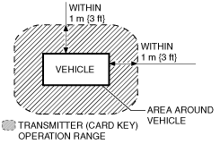
• Did the customer activate the transmitter (card key) within operative area (Within 1 m {3 ft}from area around vehicle)?
|
Yes
|
Go to the next step.
|
 |
No
|
The system is normal.
Explain to the customer that the system does not work without the system operative area.
|
|
3
|
• Did the customer use the keyless entry system in particular area, such as being near TV towers, power plants, power lines, or factories?
|
Yes
|
The system is normal.
Area of operation is subject.
Explain effect of outside interference on the transmitter (card key) to the customer.
|
|
No
|
Go to the next step.
|
|
4
|
• Did the customer activate the keyless entry system with all following conditions satisfied?
-
― All doors and trunk closed.
-
― Mechanical key is not in steering lock unit.
-
― Start knob is at LOCK position.
-
― Start knob is not pressed.
|
Yes
|
Go to the next step.
|
|
No
|
The system is normal. Explain to the customer that the system does not work without these conditions satisfied.
|
|
5
|
• Are any of the following after-market electrical parts on the vehicle?
-
― Cellular phone
― Radio-wave equipment
― Remote engine starter
― TV
― Other
|
Yes
|
Go to the next step.
|
|
No
|
Go to Step 7.
|
|
6
|
• Disconnect the after-market electrical parts connectors and attempt to lock/unlock the doors with the transmitter (card key).
• Does the keyless entry system work?
|
Yes
|
The system is normal. The after-market electrical parts are interfering with the keyless entry system.
|
|
No
|
Go to the next step.
|
|
7
|
• Is there repair record of the customer's keyless entry system?
|
Yes
|
Go to the next step.
|
|
No
|
Go to Step 10.
|
|
8
|
• Does the malfunction occur after the repair?
|
Yes
|
Go to the next step.
|
|
No
|
Go to Step 10.
|
|
9
|
• Is the malfunction corrected when the ID numbers for all the customer's transmitters are updated?
|
Yes
|
System is normal. (Explain to the customer that the malfunction occurred because all the transmitter ID numbers were not updated even though the body control module or a transmitter was replaced in the previous servicing.)
|
|
No
|
Go to the next step.
|
|
10
|
• Visually inspect the transmitter (card key) battery for the following:
-
― Battery direction (polarity)
― Battery type (CR2025)
― Corrosion, soiling, deformation of battery terminals (plus/minus terminals).
― Contact malfunction between the battery terminal and battery when battery is inserted
• Is there any malfunction?
|
Yes
|
Battery insertion direction, battery type problem:
• Properly install the battery or replace the battery with a specified one (CR2025), then go to the next step.
Battery terminal malfunction:
• Clean corrosion and soiling or repair the terminal, then go to the next step.
|
|
No
|
Go to Step 12.
|
|
11
|
• Does the keyless entry system operate properly?
|
Yes
|
Troubleshooting completed.
|
|
No
|
Go to the next step.
|
|
12
|
-
Note
-
• Use a new monitor battery (normal battery) or one from another vehicle which operates normally.
• Replace the battery in all the transmitters (card key) with a monitor-use battery (normal battery).
• For each transmitter (card key), verify that the transmitter (card key) operation indicator light (LED) illuminates when a button is operated.
• Does operation indicator light (LED) for each transmitter (card key) operate?
|
Yes
|
Go to the next step.
|
|
No
|
If the operation indicator light (LED) does not illuminate, replace the transmitter (card key), then go to Step 24.
|
|
13
|
-
Note
-
• Inspect for all transmitters (card key).
• Inspect while the batteries for all of the transmitters (card key) are replaced with monitor-use batteries (normal battery).
• Verify the operation of keyless entry system using all of the transmitters (card key).
• Does the keyless entry system operate normally?
|
Yes
|
Replace the battery, then go to Step 24.
|
|
No
|
Go to the next step.
|
|
14
|
• Inspect for the keyless receiver installation.
• Is the bracket securely installed on the keyless receiver?
|
Yes
|
Go to the next step.
|
|
No
|
Install the bracket securely, and then go to the next step.
|
|
15
|
• Turn the ignition switch to the LOCK position.
• Measure the voltage at keyless receiver terminal A?
• Is the voltage B+?
|
Yes
|
Go to the next step.
|
|
No
|
• Inspect ROOM 15 A fuse.
• Inspect and repair the wiring harness between the fuse block and the keyless receiver as necessary.
|
|
16
|
• Measure the voltage at keyless receiver terminal E?
• Is the voltage 0 V?
|
Yes
|
Go to the next step.
|
|
No
|
• Inspect and repair the wiring harness between the ground wire and the keyless receiver as necessary.
• Re-tighten the ground wire as necessary.
|
|
17
|
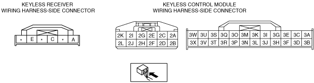
• Disconnect the keyless receiver connector (6-pin) and keyless control module connector (75-pin).
• Is there continuity between the following terminals?
-
― Keyless receiver connector terminal A—keyless control module connector terminal 3A
― Keyless receiver connector terminal C—keyless control module connector terminal 3C
|
Yes
|
Go to the next step.
|
|
No
|
• Inspect and repair the wiring harness between the keyless control module and the keyless receiver, then go to the next step.
|
|
18
|
• Remove the key from steering lock.
• Measure the pulse profile using an oscilloscope at the keyless control module terminal 3C while operating the transmitter (card key).
• Is the pulse profile become long at moment of transmitter operation?
|
Yes
|
Go to the next step.
|
|
No
|
Replace the keyless receiver, and then go to the next step.
|
|
19
|
• Measure the voltage at the keyless contorl module terminals 2A, 2C and 2E.
-
― Terminal 2C: IG1 voltage
― Terminal 2A: B+
― Terminal 2E: ACC voltage
• Is the voltage as above?
|
Yes
|
Go to the next step.
|
|
No
|
• Inspect for fuse.
• Inspect and repair the wiring harness between the keyless control module and the fuse block as necessary.
• Then go to the next step.
|
|
20
|
• Measure the voltage at keyless control module terminal 2C?
• Is the voltage 0 V?
|
Yes
|
Go to the next step.
|
|
No
|
• Inspect and repair the wiring harness between the ground wire and the keyless control module as necessary.
• Re-tighten the ground wire as necessary.
• Then go to the next step.
|
|
21
|
• Turn the start knob to LOCK position with mechanical key is not in ignition switch, and the start knob is not pushed.
• Measure the voltage following keyless control module connector.
-
― Terminal 3F (key reminder switch): below 1.0 V
― Terminal 3E (start knob (push switch)) : below 1.0 V
― Terminal 2E (ACC voltage): below 1.0 V
― Terminal 2C (IG1 voltage): below 1.0 V
• Is the signal voltage normal?
|
Yes
|
Go to the next step.
|
|
No
|
• Inspect for key reminder switch.
• Inspect and repair the wiring harness between the steering lock unit (key reminder switch) and the keyless control module.
• Then go to the next step.
|
|
22
|
• Monitor the following PIDs for the keyless control module using the M-MDS:
-
― DRSW_D (Door switch (driver's door))
― DRSW_ALL (Door switch (except driver's door))
― TR/LG_SW (Trunk compartment light switch (4SD)/Cargo compartment light switch (5HB))
• Does each monitor value agree with the door open/close condition?
|
Yes
|
• Inspect for open or short circuit in wiring harness between keyless control module terminal 3Q terminal and PJB terminal J-04 F.
-
― If the wiring harness is not normal, repair or replace malfunctioning part.
― If the wiring harness is normal, go to the next step.
|
|
No
|
• Inspect door switch for suspect door.
• Inspect for open or short circuit in wiring harness between suspect door switch and door lock control module.
|
|
23
|
• Measure the voltage at the PJB terminals J-05 AP and J-05 Y while operating the transmitter.
-
― Lock all doors with the transmitter (card key): 1.0 V or less→B+→1.0 V or less (terminal J-05 AP)
― Unlock all door with the transmitter (card key): 1.0 V or less→B+→1.0 V or less (terminal J-05 Y)
• Is the voltage as above?
|
Yes
|
• Inspect and repair the wiring harness between the PJB and the door lock actuator.
• Inspect for door lock actuator.
|
|
No
|
Replace the door lock control module.
|
|
24
|
• Does the keyless entry system operate properly?
|
Yes
|
Troubleshooting completed. Explain repairs to the customers
|
|
No
|
Re-inspect the malfunction symptoms, then repeat form Step 1 if malfunction recurs.
|