 |
am3zzw00009653
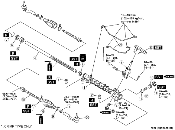
STEERING GEAR AND LINKAGE ASSEMBLY
id061400801200
1. Assemble in the order indicated in the table.
am3zzw00009653
|
|
1
|
Gear housing
|
|
2
|
Mounting rubber
|
|
3
|
Oil seal
(See Oil Seal Assembly Note.)
|
|
4
|
Steering rack
(See Steering Rack Assembly Note.)
|
|
5
|
Rack bushing
(See Rack Bushing Assembly Note.)
|
|
6
|
Stopper
(See Stopper Assembly Note.)
|
|
7
|
Clip
|
|
8
|
Pinion shaft and valve housing component
|
|
9
|
Locknut (pinion shaft side)
|
|
10
|
Housing cover
(See Housing Cover Assembly Note.)
|
|
11
|
Support yoke
|
|
12
|
Yoke spring
|
|
13
|
Adjusting cover
|
|
14
|
Locknut (adjusting cover)
|
|
15
|
Tie rod
|
|
16
|
Boot
(See Boot Assembly Note.)
|
|
17
|
Boot band
|
|
18
|
Boot clamp
|
|
19
|
Locknut
|
|
20
|
Tie-rod end
|
|
21
|
Oil pipe
|
|
22
|
Return pipe
|
|
23
|
Floor seal
(See Floor Seal Assembly Note.)
|
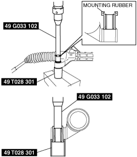
Mounting Rubber Assembly Note
1. Apply soapy water to the rubber part of the mounting rubber.
2. Install the mounting rubber so that two notches of the mounting rubber are parallel to the steering rack.
3. Press the mounting rubber until the mounting rubber end comes out completely from the gear housing using the SSTs and a press.
am3zzw00002883
|
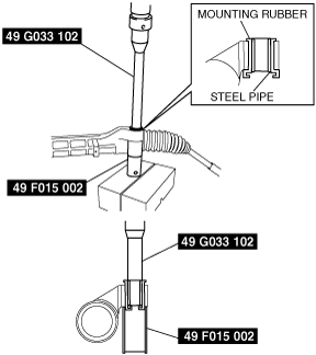
4. Reverse the gear housing, then press the mounting rubber until the mounting rubber end comes out completely from the other side. At this time, make sure that the mounting rubber and steel pipe are aligned.
am3zzw00002884
|
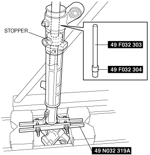
Oil Seal Assembly Note
1. Apply ATF to the lip of a new oil seal.
2. Install the SST (49 N032 319A) to the gear housing with the raised part facing up as shown in the figure.
3. Set the stopper into the gear housing to hold the SSTs as shown in the figure.
am3zzw00009660
|
4. Install the oil seal using the SSTs (49 F032 303, 49 F032 304) and a press.
Steering Rack Assembly Note
1. Apply multipurpose grease to the rack teeth.
2. Install a plastic bag to the rack teeth and insert the steering rack in the gear housing.
am3zzw00001717
|
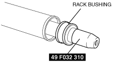
Rack Bushing Assembly Note
1. After installing the SST to the steering rack end, assemble the rack bushing to the rack housing.
am3zzw00001718
|
Stopper Assembly Note
1. Assembly the stopper.
2. Inspect airtightness.
am3zzw00001716
|
Pinion Shaft and Valve Housing Component Assembly Note
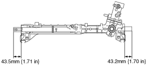
1. Set the rack in the center with the measurement between rack housing end and rack end as shown in the figure.
am3zzw00001719
|
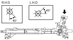
2. When the pinion shaft position is as shown in the figure with the rack in the center, insert the pinion shaft and valve housing component.
am3zzw00001720
|
Housing Cover Assembly Note
1. Apply silicone sealant to the threads of the housing cover.
2. Assemble the housing cover.
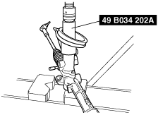
Adjusting Cover Assembly Note
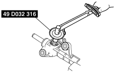
1. Apply sealant to the threads of the adjusting cover.
2. Using the SST, tighten the adjusting cover with a tightening torque of 20.0 N·m {2.0 kgf·m, 14.8 ft·lbf}.
am3zzw00001721
|
3. Using the SST, loosen the adjusting cover to 25—30°.
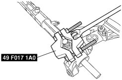
Locknut (Adjusting Cover) Assembly Note
1. Fix the adjusting cover and tighten the locknut.
am3zzw00009661
|
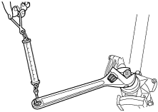
2. Measure the rotation torque of the pinion shaft using a crescent wrench and pull scale.
am3uuw00001414
|
am3uuw00001415
|
3. If not as specified, remove the locknut and adjust the adjusting cover.
Boot Assembly Note
1. Apply silicone grease to the rubber lip groove.
2. Assemble the boot.
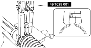
Boot Band (Crimp Type) Assembly Note
1. Assemble the boot band to the boot.
2. Crimp the boot band using the SST.
am3zzw00009650
|
3. Rotate the boot by hand and verify that it is securely installed to the boot band.
Floor Seal Assembly Note
1. Assemble the floor seal using the SST and a press.
am3zzw00009662
|