 |
am3zzw00004810
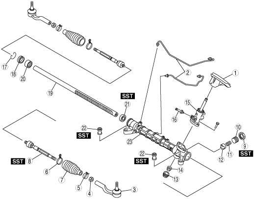
STEERING GEAR AND LINKAGE DISASSEMBLY
id061400801000
1. Disassemble in the order indicated in the table.
am3zzw00004810
|
|
1
|
Floor seal
|
|
2
|
Oil pipe
|
|
3
|
Tie-rod end
(See Tie-rod End Disassembly Note.)
|
|
4
|
Locknut
|
|
5
|
Boot clamp
|
|
6
|
Boot band
|
|
7
|
Boot
|
|
8
|
Tie rod
(See Tie Rod Disassembly Note.)
|
|
9
|
Locknut (adjusting cover)
|
|
10
|
Adjusting cover
|
|
11
|
Yoke spring
|
|
12
|
Support yoke
|
|
13
|
Housing cover
|
|
14
|
Locknut (pinion shaft side)
|
|
15
|
Pinion shaft and valve housing component
|
|
16
|
Return pipe
|
|
17
|
Clip
|
|
18
|
Stopper
|
|
19
|
Steering rack
|
|
20
|
Rack bushing
|
|
21
|
Oil seal
(See Oil Seal Disassembly Note.)
|
|
22
|
Mounting rubber
|
|
23
|
Gear housing
|
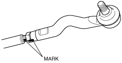
Tie-rod End Disassembly Note
1. Place alignment marks as shown in the figure for proper installation.
am3zzw00001727
|
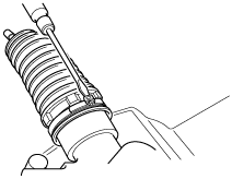
Boot Band (Crimp Type) Disassembly Note
1. Insert a flathead screw driver into the boot band as shown in the figure, then press the caulked area outward to remove the boot band.
am3zzw00009649
|
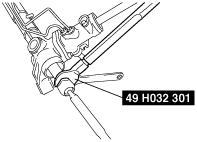
Tie Rod Disassembly Note
1. Fix the steering rack and remove the tie rod using the SST.
am3zzw00001728
|
Locknut (Adjusting Cover), Adjusting Cover Disassembly Note
1. Remove the locknut using the SST.
am3zzw00001729
|
2. Remove the adjusting cover.
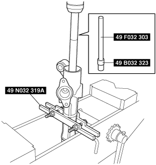
Oil Seal Disassembly Note
1. Install the SST (49 N032 319A) to the gear housing with the raised part facing up as shown in the figure.
2. Insert the SSTs (49 F032 303, 49 B032 323) into the valve housing side.
3. Remove the oil seal using a press.
am3zzw00001730
|
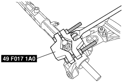
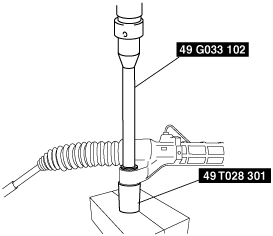
Mounting Rubber Disassembly Note
1. Press the mounting rubber out from the gear housing using the SSTs and a press.
am3zzw00002879
|