 |
am3zzw00003495
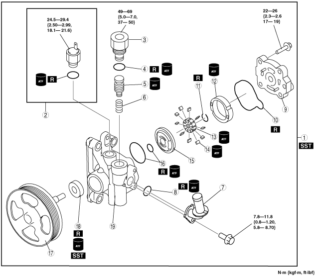
POWER STEERING OIL PUMP DISASSEMBLY/ASSEMBLY[L3 Turbo]
id0614008008c3
1. Disassemble in the order indicated in the table.
2. Assemble in the reverse order of disassembly.
am3zzw00003495
|
|
1
|
Power steering oil pump component
|
|
2
|
Pressure switch component
|
|
3
|
Connector
|
|
4
|
O‐rings
|
|
5
|
Control valve
|
|
6
|
Spring
|
|
7
|
Suction pipe
|
|
8
|
O‐ring
|
|
9
|
Rear pump body
(See Rear Pump Body Assembly Note.)
|
|
10
|
O-ring
|
|
11
|
Clip
|
|
12
|
Cam ring
(See Cam Ring Assembly Note.)
|
|
13
|
Rotor
(See Rotor Assembly Note.)
|
|
14
|
Vane
|
|
15
|
Side plate
(See Side Plate Assembly Note.)
|
|
16
|
O‐ring
|
|
17
|
Shaft component
|
|
18
|
Oil seal
(See Oil seal Disassembly Note.)
(See Oil Seal Assembly Note.)
|
|
19
|
Front pump body
|
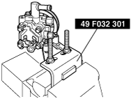
Power Steering Oil Pump Component Disassembly Note
1. Secure the power pressure oil pump using the SST.
am8rrw00000898
|
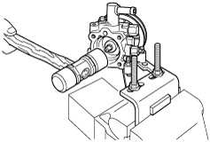
Shaft Assembly Disassembly Note
1. Using a plastic hammer, tap out the shaft component from the front pump body.
am8rrw00000899
|
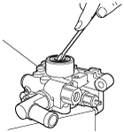
Oil seal Disassembly Note
1. Remove the oil seal from the front pump body using a flathead screwdriver.
am8rrw00000900
|
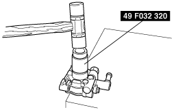
Oil Seal Assembly Note
1. Install the oil seal in the front pump body using the SST and plastic hammer.
am3uuw00000123
|
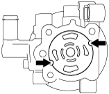
Side Plate Assembly Note
1. Install the side plate in the position shown in the figure.
am8rrw00000902
|
Rotor Assembly Note
1. Install to the front pump body so that area B of the groove is on the rear pump body side as shown in the figure.
am8rrw00000903
|
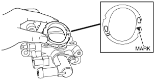
Cam Ring Assembly Note
1. Install the cam ring in the front pump body with the mark facing upward.I
am8rrw00000904
|
Rear Pump Body Assembly Note
1. After installing the rear body, manually turn the shaft to verify that it rotates smoothly.