|
1
|
VERIFY FREEZE FRAME DATA HAS BEEN RECORDED
• Has the FREEZE FRAME DATA been recorded?
|
Yes
|
Go to the next step.
|
|
No
|
Record the FREEZE FRAME DATA on the repair order, then go to the next step.
|
|
2
|
VERIFY RELATED REPAIR INFORMATION AVAILABILITY
• Verify related service repair information availability.
• Is any related repair information available?
|
Yes
|
Perform repair or diagnosis according to the available repair information.
• If the vehicle is not repaired, go to the next step.
|
|
No
|
Go to the next step.
|
|
3
|
VERIFY CURRENT SIGNAL STATUS: IS CONCERN INTERMITTENT OR CONSTANT?
• Connect the M-MDS to the DLC-2.
• Clear the DTC from the PCM memory using the M-MDS.
• Run the vehicle under the FREEZE FRAME DATA stored condition.
• Is the same DTC present?
|
Yes
|
Go to the next step.
|
|
No
|
Intermittent concern exists.
Perform the “INTERMITTENT CONCERNS TROUBLESHOOTING”.
|
|
4
|
VERIFY CURRENT SIGNAL STATUS: IS CONCERN INTERMITTENT OR CONSTANT?
• Connect the M-MDS to the DLC-2.
• Clear the DTC from the PCM memory using the M-MDS.
• Run the vehicle under the FREEZE FRAME DATA stored condition.
• Is the same DTC present?
|
Yes
|
Go to the next step.
|
|
No
|
Intermittent concern exists.
Perform the “INTERMITTENT CONCERNS TROUBLESHOOTING”.
|
|
5
|
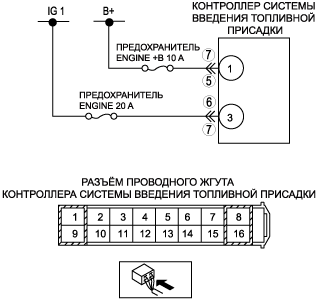
INSPECT POWER SUPPLY CIRCUIT
• Turn the engine switch to off.
• Measure voltage between fuel additive control module terminal 1 (wiring harness-side) and body ground.
• Is the voltage B+?
|
Yes
|
Go to the next step.
|
|
No
|
Repair or replace the wiring harness, then go to Step 8.
|
|
6
|
INSPECT IG1 SIGNAL CIRCUIT
• Turn the engine switch to the ON position.
• Measure voltage between fuel additive control module terminal 3 (wiring harness-side) and body ground.
• Is the voltage B+?
|
Yes
|
Go to the next step.
|
|
No
|
Repair or replace the wiring harness, then go to Step 8.
|
|
7
|
INSPECT FUEL ADDITIVE CONTROL MODULE CONNECTOR FOR POOR CONNECTION
• Disconnect fuel additive control module connector.
• Inspect for poor connection (such as damaged, pulled-out terminals, corrosion).
• Is there any malfunction?
|
Yes
|
Repair terminals, then go to Step 8.
|
|
No
|
Go to the next step.
|
|
8
|
VERIFY THAT DTC B1318 TROUBLESHOOTING IS COMPLETED
• Make sure to reconnect all disconnected connectors.
• Clear DTC from PCM memory using M-MDS.
• Run the vehicle under the FREEZE FRAME DATA stored condition.
• Is the same DTC present?
|
Yes
|
Replace the Fuel additive control module, then go to the next step.
|
|
No
|
Go to the next step.
|
|
9
|
VERIFY AFTER REPAIR PROCEDURE
• Perform the after repair procedure.
• Are any DTCs present?
|
Yes
|
Go to the applicable DTC inspection.
|
|
No
|
DTC troubleshooting completed.
|